


Gas Supply
Check all local codes for requirements, especially for the size and type of gas supply line required. On natural gas lines less than
15” (380 mm) long, use 1/2” tube; on longer runs, use 3/4” iron tube or equal. On LP gas lines, consult LP gas supplier.
Installing a New Main Gas Shutoff Valve
Each appliance should have its own manual gas shutoff valve. A manual main gas shutoff valve should be located in the vicinity
of the furnace. Where none exists, or where its size or location is not adequate, contact your local authorized installer for
installation or relocation.
Compounds used on threaded joints of gas piping must be resistant to the action of propane (LP) gas. The gas lines must be
checked for leaks by the installer. This should be done with a soap solution watching for bubbles on all exposed connections,
and if unexposed, a pressure test should be made. Repair all leaks prior to operating the furnace.
Never use an exposed flame to check for leaks. Appliance must be disconnected from piping at inlet of control valve
and pipe capped or plugged for a pressure test. Never pressure test with appliance connected; the control valve will
sustain damage!
A gas shutoff valve and ground joint union should be installed in the gas line upstream of the gas control to aid in servicing. It is
required by the National Fuel Gas Code that a drip line be installed near the gas inlet. This should consist of a vertical length of
pipe tee connected into the gas line that is capped on the bottom in which condensation and foreign particles may collect.
The use of the following gas connectors is recommended:
– ANSI Z21.24 Appliance Connectors of Corrugated Metal Tubing and Fittings, CGA 6.10
– ANSI Z21.45 Assembled Flexible Appliance Connectors of Other than All–Metal Construction.
The above connectors may be used if accepted by the local codes or authority having jurisdiction.
Pressure Testing of the Gas Supply System
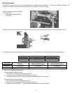
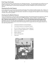
1. To check the inlet pressure to the gas valve, a plugged tapping, accessible for test gauge connection, is provided on the
gas valve (Figure 8).
2. The appliance and its individual shutoff valve must be disconnected from the gas supply piping system during any pressure
testing of in excess of 1/2 psig (3.5 kPa).
3. The appliance must be isolated from the gas supply piping system by closing its individual manual shutoff valve during any
pressure testing of the gas supply piping system at test pressures equal to or less than 1/2 psig (3.5 kPa).
Attention: If any of the above procedures results in pressures in excess of 1/2 psig (14” w.c., 3.5 kPa) on the appliance gas
valve, it will result in a hazardous condition.
High Altitudes (U.S. Only)
For altitudes/elevations above 2,000 feet (610 m), ratings should be reduced at the rate of 4 percent for each 1,000 feet (305 m)
above sea level by reducing the manifold pressure at a rate of 8% on the gas supply. Maximum altitude allowed for installation is
5,500 feet (1680 m).
High Altitudes (Canada Only)
The appliance is tested according to CGA 2.17 M91 for installation between 0 and 4,500 feet (0 and 1370 m) altitude. For
altitudes/elevations above 2,000 feet (610 m), ratings should be reduced at the rate of 4 percent for each 1,000 feet (305 m)
above sea level by reducing the manifold pressure at a rate of 8% on the gas supply. Maximum altitude allowed for installation is
5,500 feet (1680 m).
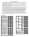
High Altitude Adjustment
Based on the altitude of the installation site, reduce the manifold pressure specified in the “Technical Data” chart and as
shown in the table below:
Manifold Pressure
Reduction Rate
Altitude
0-2,000 ft 0%
2,000-3,000 ft 8%
3,000-4,000 ft 16%
4,000-5,000 ft 24%
5,000-5500 ft 32%
9