


8
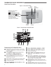
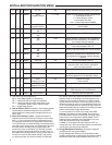
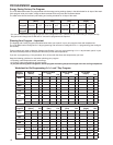
INSTALLER/CONFIGURATION MENU
Record the number you select for future use.
Press MENU or RunSched to exit the menu. The security
feature you select will start. The system button will remain
active for 10 seconds to allow setting Heat, Off, Cool or
Auto.
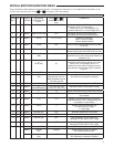
23) Limited Heat Range – This feature provides a maximum
setpoint temperature for heat. The default setting is 90°F. It
can be changed between 62°F and 98°F by pressing the
or button.
24) Limited Cool Range – This feature provide a minimum
setpoint temperature for cool. The default setting is 45°F. It
can be changed between 46°F and 82°F by pressing the
or button.
25) Select Compressor Off (CO) Feature Using Outdoor
Sensor (dF) – This feature is applicable only in heat pump
modes and with an outdoor sensor installed and enabled.
When CO is enabled by selecting a temperature >5°F
(01-15°C), the thermostat will use the outdoor sensor
temperature to determine when to switch to gas heat and
shut down the compressor.
Select DF setting (dF) – With CO selected >5, select the
setting for outdoor temperature. When the outdoor tem-
perature goes below the setpoint, the gas heat will begin.
Default is 5 (Off or disabled), but can be set in the range
of 6 to 50 using the
or buttons.
Select dF or EA – Select dF (default) if your system has
a fossil fuel (gas or oil) Auxiliary heat. Select EA if your
system has Electro Auxiliary heat and you want the com-
pressor to continue to run while calling for Auxiliary stage.
Select Compressor Delay (Cd) – After the auxiliary heat
is turned on, the compressor(s) shut down is delayed for
the time selected (in seconds). This delay is factory set
to 60, but can be set in the range of 0 to 99 using
or
buttons.
26) Select Auxiliary Off (AO) – Select the temperature that
will inhibit the auxiliary heating stage. As long as the out-
door temperature is above the setpoint, the auxiliary heat
will not turn on. The default setting is 80, but can be set in
the range of 35 to 79. A setting of 80 disables this feature.
27) Economizer Feature – This item allows longer Y1 cycles
for cooling with outdoor air.
28)Pre-occupancy Purge (PP) – Selects the number of
hours the pre-occupancy purge time from 0 to 1, 2 or 3
hour with the
or buttons.
When the pre-occupancy purge time is greater than 0
hours, the blower output ("G" terminal) will energize the
number of pre-occupancy purge hours before the next
programmed occupancy time period. During this pre-
purge time the A1 terminal will be energized.
29) Select Filter Replacement Reminder and Set Run Time
Select the "Change Filter" reminder On or OFF. If se-
lected On, press MENU to select the time period from 25
to 1975 hours in 25 hours increments. In a typical system,
200 hours (default) of run time is approximately 30 days.
After the selected time of blower operation, the thermostat
will display "Change Filter" as a reminder to change or
clean your air fi lter. When "Change Filter" is displayed,
press MENU or RUN SCHED button to clear the display
and restart the time to the next fi lter change.
30) Change UV Lamp – This feature allows the thermostat
to display the words Change UV Lamp (Call for Service
of UV bulb) after a set time of UV bulb operation. This is
a reminder to maintain your UV system at optimum level
of operation. When enabled the factory set interval for
Change UV Lamp to be displayed is 350 days of UV bulb
operation and can be adjusted in 25 day increments. This
should be adjusted with respect to the bulb's recommend-
ed maintenance schedule.
When Change UV Lamp is displayed, you can clear it by
pressing MENU.
31) Select Reversing Valve Output – The O/B option is
factory set at "O" position. This will accommodate the
majority of heat pump applications, which require the
changeover relay to be energized in COOL. If the thermo-
stat you are replacing or the heat pump being installed
with this thermostat requires a "B" terminal, to energize
the changeover relay in HEAT, the O/B option should be
set at "B" position.
OPERATING YOUR THERMOSTAT
If at any time during testing your system does not operate
properly, contact a qualifi ed service person.
Fan Operation
If your system does not have a G terminal connection, skip to
Heating System.
1. Turn on power to system.
2. Move FAN switch to ON position. The blower should begin
to operate.
3. Move FAN switch to AUTO position. The blower should
stop immediately.
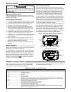
To prevent static discharge problems, touch side of
thermostat to release static build-up before touching
any keys.
NOTE
Check Thermostat Operation
Do not allow the compressor to run unless the com-
pressor oil heaters have been operational for 6 hours
and the system has not been operational for at least
5 minutes.
CAUTION
!
Heating System
1. Press SYSTEM button to select HEAT. If the auxiliary
heating system has a standing pilot, be sure to light it.
2. Press to adjust thermostat setting to 1° above room
temperature. The heat pump system should begin to oper-
ate. The display should show “System On”. However, if
the system confi guration is set to HP1 or HP2 and setpoint
temperature display is fl ashing, the 5 minute compressor
lockout feature is operating (see Confi guration menu,
item 11).
3. Adjust temperature setting to 3° above room temperature.
If your system confi guration is set at MS2, HP2 or HP1,
the auxiliary heat system should begin to operate and
the display will show “System On +2”.
4. Press to adjust the thermostat below room tempera-
ture. The heating system should stop operating.