


2
Remove Old Thermostat
Before removing wires from old thermostat, mark wires for
terminal identifi cation so the proper connections will be made
to the new thermostat.
Installing New Thermostat
1. Pull the thermostat body off the thermostat base. Forcing
or prying on the thermostat will cause damage to the unit.
2. Place base over hole in wall and mark mounting hole
locations on wall using base as a template.
3. Move base out of the way. Drill mounting holes. If you
are using existing mounting holes and the holes drilled
are too large and do not allow you to tighten base snug-
ly, use plastic screw anchors to secure the base.
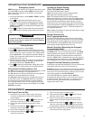
4. Fasten base snugly to wall using mounting holes shown
in Figure 1 and two mounting screws. Leveling is for
appearance only and will not affect thermostat operation.
5. Connect wires to terminal block on base using appropriate
wiring schematic.
6. Push excess wire into wall and plug hole with a fi re re-
sistant material (such as fi berglass insulation) to prevent
drafts from affecting thermostat operation.
7. Carefully line the thermostat up with the base and snap
into place.
Battery Location
2 "AA" alkaline batteries are included in the thermostat at the
factory with a battery tag to prevent power drainage. Remove
the battery tag to engage the batteries.
To replace batteries, set system to OFF, remove thermostat
from wall and install the batteries in the rear along the top of
the thermostat (see Figure 1). For best results, use a premi-
um brand "AA" alkaline battery such as Duracell
®
or Ener-
gizer
®
. If the home is going to be unoccupied for an extended
period (over 3 months) and
is displayed, the batteries
should be replaced before leaving.
WIRING CONNECTIONS
Refer to equipment manufacturers' instructions for specifi c
system wiring information. After wiring, see CONFIGURA-
TION section for proper thermostat confi guration.
Wiring diagrams shown are for typical systems and describe
the thermostat terminal functions.
WARNING
!
Thermostat installation and all components of the
control system shall conform to Class II circuits per
the NEC code.
INSTALLATION
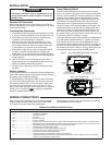
Power Stealing Switch
This thermostat is designed for 24 VAC power to be hard-
wired via a common connection to the C terminal with battery
back-up. The thermostat also has the capability to be battery
powered with the battery power supplemented by Power
Stealing to extend the battery life. Powered only by the two
"AA" batteries the expected battery life is about one year.
With battery power supplemented by the Power Stealing
circuits the battery life can be extended up to fi ve years. The
supplemental power is derived from the Heating (W) and/or
Cooling (Y) circuits. The thermostat will utilize either one or
both of these circuits to supplement the battery power. The
thermostat "steals" power from these circuits when the circuit
is not active (calling for heating or cooling).
The Power Stealing switches are defaulted to the ON position.
If the thermostat is hardwired with "C" common connection,
both switches should be moved to the OFF position. If the
thermostat is battery powered and the heating or cooling sys-
tem does not cycle, indicating the system is not compatible,
the switch for the circuit, heating or cooling, experiencing the
incompatibility should be moved to the OFF position.
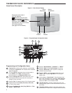
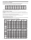
Figure 1 – Thermostat Base Multi-Stage 1F95-0680
Rear view of thermostat
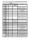
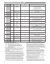
TERMINAL DESIGNATION DESCRIPTIONS
Terminal Designation Description
O/B ........................................... Changeover valve for heat pump energized constantly in cooling and off/heating
Y2 ............................................ 2nd Stage Compressor
Y ............................................ Compressor Relay
G ............................................ Fan Relay
RC ............................................ Power for Cooling
RH ............................................ Power for Heating
C ............................................ Common wire from secondary side of cooling (Optional). Required for fault indication, continuous back-
light operation or remote temperature sensor operation 6 Powered closed 3rd wire for 3-wire zone valve
W/E ........................................... Heat Relay/Emergency Heat Relay (Stage 1) (3rd Stage Heat in HP2)
W2 ............................................ 2nd Stage Heat (4th Stage Heat in HP2)
- ............................................ Common (DC) for wired remote temperature sensor
S ............................................ Frequency signal from remote temperature sensor
+ ............................................ Power (DC) to remote temperature sensor
A1 ............................................ Output energized in occupied (Morn, Day, and Eve periods)
L ............................................ Compressor diagnostic indicator for systems with diagnostic connection typically found on Heat pump
systems or with Copeland's Comfort Alert
2 "AA" Batteries
Power Stealing
Switches
Mounting
Hole
Mounting
Hole
Place Level
across Mounting Tabs
(for appearance only)
Place Level
across Mounting Tabs
(for appearance only)