


12
Wired Remote Temperature Sensing
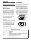
One remote temperature sensor can be installed indoor or
outdoor and connected to the thermostat by a maximum
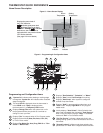
cable length of 100 meters (300 feet). Terminals +, S and - on
the terminal block allow connection of the remote sensor.
The thermostat must have 24 VAC Common connection to
terminal C for the remote sensor to operate. The remote sen-
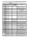
sor can be enabled or disabled in the Installer/Confi guration
menu, item 26.
When remote sensor, Remote, is selected Off (factory de-
fault), no remote sensor is enabled. When remote sensor is
selected On, the next step is to select the remote as indoor,
Remote In, or outdoor, Remote Outdoor. If the remote is se-
lected as Remote In, an additional step will be to select if the
temperature shown on the display will be from the thermostat,
LS On, or the remote sensor LS Off.
In normal operation, when a remote sensor is enabled the
time digits of the display will alternate between the time and
the remote temperature for three seconds each. Above the
remote temperature will be Remote, for indoor sensor or
Outdoor Remote, for outdoor sensor. If the remote sensor is
an indoor sensor and the local display has been disabled, the
temperature displayed as the room temperature will be the
remote sensor temperature.
Sensing Range:
Outdoor temperature range is -40
o
F to 140
o
F
Indoor temperature range is 32
o
F to 99
o
F
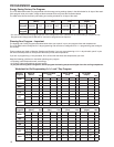
Weighing of Remote Reading:
The thermostat will weight or average the temperature of the
indoor remote sensor with the local sensor in the thermostat
for each program period. The averaging will be active only
when the local sensor and the indoor remote sensor are both
functional and enabled in the Installer/Confi guration menu.
When the thermostat is in the Set Schedule mode, the weight
of the indoor sensor will be shown in the current temperature
digits of the display. The weight will show as A2 (average and
default), H4 (high) or L1 (low). Pressing the
or but-
tons at the same time will change the weight for the program
period. The weight of the thermostat sensor is fi xed.
In normal operation of the thermostat, the current tempera-
ture displayed will be the weighted average of the local
sensor and the remote sensor using the formula (local sensor
weight x local sensor temperature) + (remote sensor weight x
remote sensor temperature) / (local sensor weight + remote
sensor weight).
Example: Local sensor temperature is 80° and the remote
sensor is 70°.
If weight is selected H4, the averaged temperature of 72° will
be displayed.
(1 x 80) + (4 x 70) / 5 = 72°
If weight is selected A2, the average temperature of 73° will
be displayed.
(1 x 80) + (2 x 70) / 3 = 73.3°
If weight is selected L1, the average temperature of 75° will
be displayed.
(1 x 80) + (1 x 70) / 2 = 75°
PROGRAMMING
The example shows that the weight selected would prioritize
the overall averaged temperature between the two sensors.
The high weight selection caused the remote sensor to have
a higher infl uence in the calculated temperature average than
the local sensor and the low weight selection caused the
remote sensor to have less infl uence.
Dual Fuel Temperature Setpoint
When the thermostat is confi gured for Heat Pump mode and
the Dual Fuel feature is selected on, the thermostat can moni-
tor the outside temperature or use software logic to determine
when to switch to gas heat and shut down the compressor.
This eliminates the need for a fossil fuel kit.
The user selectable temperature is called the dual fuel tem-
perature setpoint, dF and is set in the Installer/Confi guration
menu, items 27 or 28. With outdoor remote sensor available,
the dual fuel temperature setpoint can be set to a tempera-
ture of 5° through 50°. When outdoor remote sensor is not
available, a software logic based dual fuel number from 01 to
09 can be selected. Cd will not be available if dF is selected
OFF.
After the dual fuel temperature setpoint is set and
is
pressed, a delay, Cd, can be set for compressor shutdown af-
ter the auxiliary stage is energized. This delay can be set from
0 seconds to 99 seconds to minimize the time that the system
may blow cooler air until the alternate source of heat comes
on. Default setting for delay is 60. When setting the delay, if
the or buttons are held depressed, the setpoint will
increase or decrease at the rate of one degree every half
second for the fi rst three seconds and double the speed after
three seconds.
Blower Balance Point
With an air to air heat pump system, the indoor circulator
blower discharge air temperature from the register is depend-
ent on outdoor temperature. When the outdoor temperature
is, for example, above 35 degrees, the discharge air is warm.
But, when the outdoor temperature drops, the discharge air
temperature also drops and is cooler. If the circulator blower
speed is reduced, the air temperature will increase and the
resident will feel warmer. The outdoor temperature compared
to the blower balance point temperature determines the
blower speed.