


4
WIRING DIAGRAMS
R
CG W
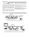
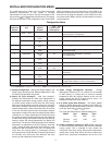
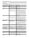
Figure 4. Typical wiring diagram for two transformer single stage systems with safety circuits in BOTH systems
Changeover
Relay*
YO/B
Compressor
Contactor
* Changeover Relay is energized in COOL when O/B switch is in the “O” position
Changeover Relay is energized in HEAT when O/B switch is in the “B” position
Heat
Relay
Fan
Relay
Optional
TWO COMMONS MUST
BE JUMPERED TOGETHER!
24 VAC 120 VAC
HOT
NEUTRAL
THERMOSTAT
SYSTEM
HOT
NEUTRAL
120 VAC
Limit or
Safety
Switches
Limit or
Safety
Switches
Limit or
Safety
Switches
24 VAC
Limit or
Safety
Switches
COMMON
COMMON
Auxiliary
Heating
Transformer
(Class II
Current Limited)
Heat Pump Tr ansformer
(Class II Current Limited)
24 VAC
ACCESSORY
RELAY N.O.
CONTACT
Polarity must be observed. If the HOT side of the
second transformer is jumpered to the COMMON side
of the first transformer a short will be made. Damage
to equipment will occur when power is restored.
NOTE
The accessory relay scheme
is required when safety
circuits exist in both systems.
NOTE
Optional Jumper for
Single Stage Heat Pump
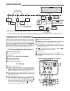
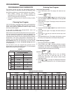
THERMOSTAT QUICK REFERENCE
Before you begin programming your thermostat, you should be
familiar with its features and with the display and the location
and operation of thethermostat buttons and switches (see
g.5).Yourthermostatconsistsoftwoparts:thethermostat
cover and the base. To remove the cover, pull it straight out
from the base. To replace the cover, line up the cover with the
base and press until the cover snaps onto the base.
The Thermostat Buttons and Switches
1
Raises temperature setting.
2
Lowers temperature setting.
3
TIME button.
4
SYSTEMswitch(COOL, OFF, HEAT, EMER).
5
PRGM(program)button.
6
FAN switch (ON, AUTO).
7
RUN/HOLD(program)button.
The Display
8
Indicates days of the week.
9
Indicates setpoint temperature. This is blank when system
switch is in the OFF position. Setpoint temperature is
displayed(ashing)ifthethermostatisinlockoutmodeto
prevent the compressor from cycling too quickly.
10
“Save”indicatestheCoolSavingsfeatureisenabledin
the configuration menu. “Save”(ashing)indicatesCool
Savingsfeatureisactive.
11
Flame icon( )isdisplayedwhentheSYSTEMswitchis
intheHEATposition.Flame icon( )isdisplayedashing
when thermostat is calling for heat. Snowflake icon( )
isdisplayed(non-ashing)whentheSYSTEMswitchis
in the COOL position. Snowflake icon( )isdisplayed
(ashing)ifthethermostatiscallingforcool.
12
Displays current temperature.
13
“Service”indicatesadiagnosticfaultintheheating/cooling
system. It does not indicate a fault in the thermostat.
14
“Change Filter” is displayed when the system has run for
the programmed filter time period as a reminder to change
or clean your air filter.
15
“ ” indicates power level of batteries. “Change ”
indicates batteries should be replaced.
16
Indicates time.
17
“A” “P” indicatestimeasMorning(A)Evening(P).
18
“Temp Hold” indicates temporary hold or “Hold” indicates
hold mode.
Figure 5. Thermostat display, buttons, and switches
SYSTEM
2
1
3
4
5
6
7
8
16
9
10
11
12
13
15
14
17
18