


3
ENERGY MANAGEMENT RECOVERY
(EMR)
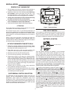
When the EMR feature is activated the thermostat’s
microcomputer calculates the time it will take to change the
room temperature to the next heat or cool program setting.
Then the thermostat will start the system before the next
programmed period so that the desired temperature is reached
atornearthebeginningoftheperiod(thethermostatcalculates
15minutesforevery1°Ftemperaturechange).Thisfeature
provides better efficiency by allowing gradual temperature
changes.
For example: The thermostat is programmed to provide an
overnight heatingtemperature of66°F,and duringthe next
program period, beginning at 6:00 AM, the programmed
temperatureis70°F.WithEMRactivated,thethermostatwill
automaticallystarttheheatingsystemat5:00AM,sothatthe
programmedtemperatureof70°Fisreached byabout6:00
AM.
If the overnight room temperature drops only to 68°F, the
thermostatwillstartthesystemat5:30toreachtheprogrammed
temperatureof70°Fat6:00.
The thermostat is shipped with the EMR feature active, which
means that the thermostat will start the heating system before
the beginning of the next program period.
To deactivate the EMR function, see the Configuration menu
onPage5).Thethermostatwillthenwaituntiltheprogrammed
time to start the system for a temperature change.
INSTALLATION
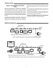
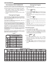
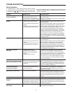
WIRING DIAGRAMS
R
C
24 VAC
120 VAC
Hot
Neutral
THERMOSTAT
SYSTEM
G W
Figure 2. Typical wiring diagram for single transformer single stage systems
TRANSFORMER
(Class II Current Limited)
Changeover
Relay*
YO/B
Compressor
Contactor
* Changeover Relay is energized in COOL when O/B switch is in the “O” position
Changeover Relay is energized in HEAT when O/B switch is in the “B” position
Heat Relay
Fan
Relay
Optional
Optional Jumper for
Single Stage Heat Pump
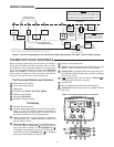
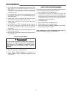
R
C
24 VAC
120 VAC
Hot
Neutral
THERMOSTAT
SYSTEM
G W
Figure 3. Typical wiring diagram for two transformer single stage systems with NO safety circuits
TRANSFORMER
(Class II Current Limited)
Changeover
Relay*
YO/B
Compressor
Contactor
* Changeover Relay is energized in COOL when O/B switch is in the “O” position
Changeover Relay is energized in HEAT when O/B switch is in the “B” position
Heat Relay
Fan
Relay
Optional
Limit or
Safety
Switches
TWO COMMONS MUST
BE JUMPERED TOGETHER!
HOT
NEUTRAL
120 VAC
24 VAC
CUT AND
TAPE OFF!
If safety circuits are in
only one of the systems,
remove the transformer
of the system with NO
safety circuits.
NOTE
Optional Jumper for
Single Stage Heat Pump