4
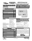
THERMOSTAT/REMOTE SENSOR QUICK REFERENCETHERMOSTAT/REMOTE SENSOR QUICK REFERENCE
THERMOSTAT/REMOTE SENSOR QUICK REFERENCETHERMOSTAT/REMOTE SENSOR QUICK REFERENCE
THERMOSTAT/REMOTE SENSOR QUICK REFERENCE
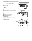
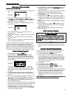
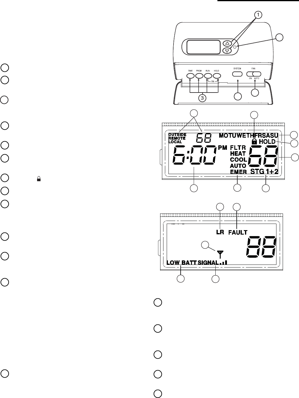
Figure 7 – Thermostat display, buttons and switchesFigure 7 – Thermostat display, buttons and switches
Figure 7 – Thermostat display, buttons and switchesFigure 7 – Thermostat display, buttons and switches
Figure 7 – Thermostat display, buttons and switches
Before operating the thermostat, familiarize yourself with the
display and button functions. Both thermostat and remote
sensor consist of two parts: the cover and the base. To remove
a cover, pull it straight out from the base. To replace a cover, line
it up with the base and press until the cover snaps into place on
the base.
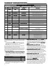
The Thermostat Buttons and Switches and DisplayThe Thermostat Buttons and Switches and Display
The Thermostat Buttons and Switches and DisplayThe Thermostat Buttons and Switches and Display
The Thermostat Buttons and Switches and Display
1
Raises and lowers the temperature setting.
2
Light flashes every 20 seconds indicating acceptable
signal reception from indoor or outdoor remote sensor.
3
Buttons for setting time (Time), programming (Prgm),
running program (Run) and bypassing program to
hold a constant temperature (Hold).
4
SYSTEM button (
COOLCOOL
COOLCOOL
COOL,
AUTOAUTO
AUTOAUTO
AUTO,
HEATHEAT
HEATHEAT
HEAT,
OFF, EMEROFF, EMER
OFF, EMEROFF, EMER
OFF, EMER
heat pump systems only).
5
FAN switch (
ONON
ONON
ON,
AUTOAUTO
AUTOAUTO
AUTO).
6
Displays the active temperature sensor (outside,
remote, local) and its sensed temperature.
7
Displays ( ) when in keypad lockout mode.
8
Indicates day of the week.
9
Indicates the thermostat mode information:
"
HOLDHOLD
HOLDHOLD
HOLD" alternates with the system mode (see item 12)
if the HOLD button is pressed to bypass the program
and maintain a constant temperature.
10
Displays currently programmed set temperature (blank
when
SYSTEM SYSTEM
SYSTEM SYSTEM
SYSTEM is
OFFOFF
OFFOFF
OFF).
11
Alternately displays the current time and the tempera-
ture average of sensors (thermostat [local] and/or
indoor remote) turned on.
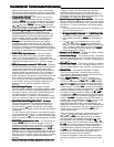
12
"
HEATHEAT
HEATHEAT
HEAT" is displayed when set to heating,
"
COOLCOOL
COOLCOOL
COOL" is displayed when set to cooling,
"
AUTOAUTO
AUTOAUTO
AUTO" is displayed when set for automatic change-
over between heating and cooling.
When "
AUTOAUTO
AUTOAUTO
AUTO" is displayed, the currently active mode
(Heat or Cool) will also display.
"
EMEREMER
EMEREMER
EMER" is displayed flashing (heat pump systems
only) when the thermostat is set to the Emergency
Mode. Emergency is used to bypass the heat pump
and use only the back-up heating system.
"
FLTRFLTR
FLTRFLTR
FLTR" is displayed as a reminder to change or clean
the air filter after system has run for the programmed
filter time period.
13
Stage 1 & 2 indicator.
"
STG 1STG 1
STG 1STG 1
STG 1" indicates when the first stage heat or cool is
energized. "
STG + 2STG + 2
STG + 2STG + 2
STG + 2" indicates when the second stage
heat or cool is energized. "+2" blinking indicates
Auxiliary Heat stages are energized on Heat Pump
Systems.
2
4
5
14
Displays "
LRLR
LRLR
LR" when the limited range feature is
activated. Limited range limits the temperature the
thermostat can be set to.
15
Indicates the system is sending a fault signal to the
thermostat "L" terminal. This does not indicate a fault
in the thermostat.
16
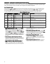
Antenna will display for a few seconds when the remote
or outdoor transmitted signal is received.
17
Displays "LOW BATT" when the 2 "AA" batteries are
low and should be replaced.
18
Indicates the current signal strength level of the remote
temperature system. Signal strength level is low (one
bar on), medium (two bars on) or high (three bars on).
The remote will operate with 1 bar showing.
8
6
9
12
7
10
1311
14
15
17
18
16


