2
ANTENNA
MOUNTING HOLE
MOUNTING HOLE
INSTALLATIONINSTALLATION
INSTALLATIONINSTALLATION
INSTALLATION
WARNING
!
Thermostat installation and all components of theThermostat installation and all components of the
Thermostat installation and all components of theThermostat installation and all components of the
Thermostat installation and all components of the
control system shall conform to Class II circuits per thecontrol system shall conform to Class II circuits per the
control system shall conform to Class II circuits per thecontrol system shall conform to Class II circuits per the
control system shall conform to Class II circuits per the
NEC code.NEC code.
NEC code.NEC code.
NEC code.
A standard heat/cool thermostat consists of three basic parts:
1. The cover, which may be either a snap-on or hinge type.
2. The base, which is removed by loosening all captive
screws.
3. The switching subbase, which is removed by unscrewing
the mounting screws that hold it on the wall or adapter
plate.
Before removing wires from old thermostat,Before removing wires from old thermostat,
Before removing wires from old thermostat,Before removing wires from old thermostat,
Before removing wires from old thermostat,
label each wire with the terminal designation fromlabel each wire with the terminal designation from
label each wire with the terminal designation fromlabel each wire with the terminal designation from
label each wire with the terminal designation from
which it was attachedwhich it was attached
which it was attachedwhich it was attached
which it was attached. Disconnect the wires from the old
thermostat one at a time.
Do not let wires fall back intoDo not let wires fall back into
Do not let wires fall back intoDo not let wires fall back into
Do not let wires fall back into
the wallthe wall
the wallthe wall
the wall.
Remove Old ThermostatRemove Old Thermostat
Remove Old ThermostatRemove Old Thermostat
Remove Old Thermostat
Locate the thermostat/sensor about 5 ft. above floor level on
an interior wall in an area that represents the average room
temperature.
Do not mount directly on or near HVAC equipment or other
sources of electrical noise.
Avoid locations close to windows or near adjoining outside
walls, doors leading outside, areas close to air registers or
their direct air flow or areas with poor circulation like alcoves.
Avoid locating the sensor on a concrete wall, junction box or
metal plate. Make sure there are no electrical wires, metal,
pipes or duct work in the part of the wall chosen for the
sensor location.
Thermostat and indoor sensor are not approved forThermostat and indoor sensor are not approved for
Thermostat and indoor sensor are not approved forThermostat and indoor sensor are not approved for
Thermostat and indoor sensor are not approved for
installation in unconditioned space.installation in unconditioned space.
installation in unconditioned space.installation in unconditioned space.
installation in unconditioned space.
Guidelines for Thermostat/Sensor LocationsGuidelines for Thermostat/Sensor Locations
Guidelines for Thermostat/Sensor LocationsGuidelines for Thermostat/Sensor Locations
Guidelines for Thermostat/Sensor Locations
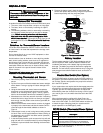
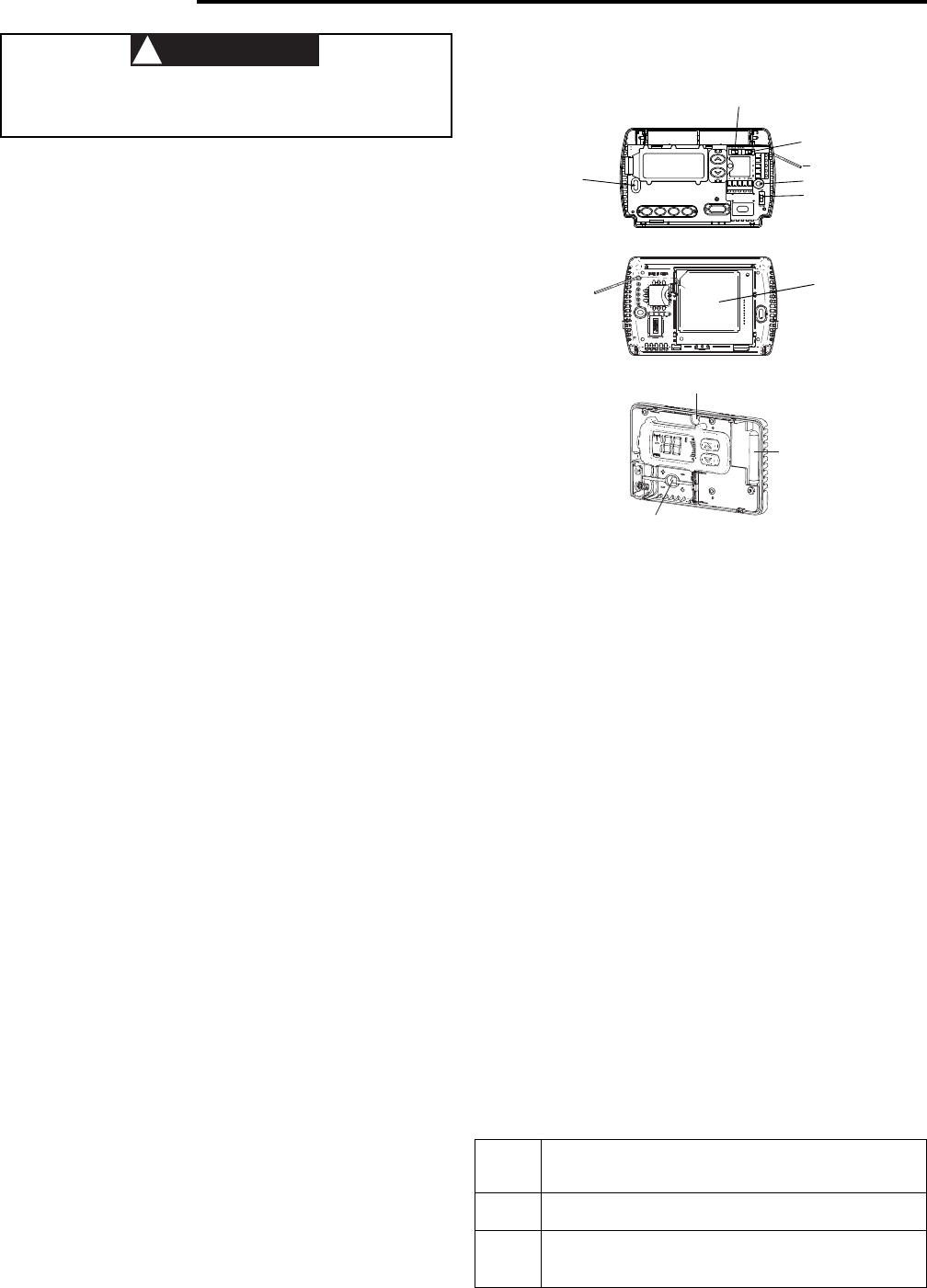
1. Remove the packing material from the thermostat and
sensor.
2. Pull the front covers of the thermostat and sensor straight
off the bases. Forcing or prying will cause damage to the
controls.
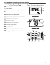
3. Using the thermostat and sensor bases as templates,
place them on the selected wall locations and mark the
location of all mounting holes (Figure 1 and 3), and the
hole for the thermostat antenna wire illustrated in Figure 2.
4. Move bases out of the way and drill the holes. If mounting
holes drilled are too large and do not allow you to tighten
base snugly, use the plastic screw anchors (provided) for
secure mounting.
5. Make sure the remote communication receiver is plugged
in properly to the thermostat and that the antenna wire is
routed through the thermostat subbase as shown in
Figure 2.
6. Fasten bases loosely to wall, using two mounting screws
for each. Place a level against bottom of base (leveling is
for appearance only and will not affect sensor operation)
and then tighten screws.
7. In the thermostat location, push excess wire into wall and
plug hole with a fire resistant material (such as fiberglass
insulation) to prevent drafts from affecting the thermostat
operation.
Mounting Thermostat and SensorMounting Thermostat and Sensor
Mounting Thermostat and SensorMounting Thermostat and Sensor
Mounting Thermostat and Sensor
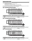
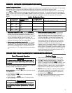
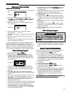
Figure 1 – Thermostat baseFigure 1 – Thermostat base
Figure 1 – Thermostat baseFigure 1 – Thermostat base
Figure 1 – Thermostat base
ELEC/GAS SWITCH
RC/PS
SWITCH
MOUNTING
HOLE
CM/NO CM
SWITCH
MOUNTING
HOLE
ANTENNA
WIRE
8. Remove the battery tags in both the thermostat and
sensor and replace the covers by lining them up with the
base and pressing until they snap into place.
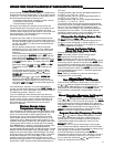
Figure 3 – Remote sensor baseFigure 3 – Remote sensor base
Figure 3 – Remote sensor baseFigure 3 – Remote sensor base
Figure 3 – Remote sensor base
The thermostat requires 2 "AA" alkaline batteries and the
sensor requires 2 "AAA" alkaline batteries. Batteries are
included at the factory with a battery tag to prevent power
drainage. The battery tag must be removed to engage the
batteries. For best results, replace batteries once a year with
new premium brand alkaline batteries such as Duracell
®
or
Energizer
®
.
Battery LocationBattery Location
Battery LocationBattery Location
Battery Location
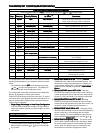
The ELEC/GAS switch is factory set to the ELEC position. In
this position, the thermostat will power the circulator fan on a
call for heat. Electric heat systems may require the switch to
be in the ELEC position.
If your system does not require that the thermostat power the
circulator fan, this switch should be set to the GAS position.
Typically, gas and oil heating systems do not require the
thermostat to power the circulator fan during a call for heat. If
your heat is gas or oil, the switch should be set to the GAS
position.
When the thermostat is configured for Heat Pump, the
thermostat will always power the circulator fan on a call for
heat in the HEAT mode. The ELEC/GAS switch must be set
to match the type of Auxiliary heat your system uses for
proper operation in the EMERgency mode.
Electric/Gas Switch (Fan Option)Electric/Gas Switch (Fan Option)
Electric/Gas Switch (Fan Option)Electric/Gas Switch (Fan Option)
Electric/Gas Switch (Fan Option)
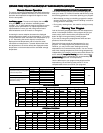
RC/PSRC/PS
RC/PSRC/PS
RC/PS
SwitchSwitch
SwitchSwitch
Switch
PositionPosition
PositionPosition
Position
DescriptionDescription
DescriptionDescription
Description
RC For Hardwire Applications. Requires Common Wire
from System Transformer to "C" Terminal on Thermostat
PS For Power Stealing Applications. Use When Common
from the System Transformer is not Available for
Connection to the "C" Terminal on the Thermostat
RC/PS Switch (Thermostat Power Option)RC/PS Switch (Thermostat Power Option)
RC/PS Switch (Thermostat Power Option)RC/PS Switch (Thermostat Power Option)
RC/PS Switch (Thermostat Power Option)
NOTE: If set to PS (Power Stealing), the thermostat "C" terminal
must notmust not
must notmust not
must not
have a wire connected.
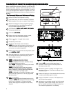
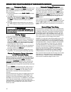
Figure 2 – Back of thermostat baseFigure 2 – Back of thermostat base
Figure 2 – Back of thermostat baseFigure 2 – Back of thermostat base
Figure 2 – Back of thermostat base
REMOTE
COMMUNICATION
RECEIVER
ANTENNA
WIRE


