


3
INSTALLATION
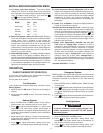
install fresh “AA” alkaline batteries immediately. For best
results, use new premium brand alkaline batteries such as
Duracell® or Energizer®. We recommend replacing batteries
every 2 years. If the home is going to be unoccupied for an
extended period (over 3 months) and
is displayed, the
batteries should be replaced before leaving. When less than
two months of battery life remain, the setpoint temperature will
offset by 10 degrees (10 degrees cooler in Heat mode / 10
degrees warmer in Cool mode). If offset occurs, the normal
setpoint can be manually reset with or . Another offset
will occur within two days if batteries are not replaced. To
replace the batteries, set system to OFF.
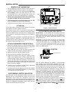
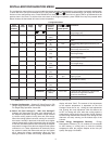
ENERGY MANAGEMENT RECOVERY
(EMR)
When the Energy Management Recovery (EMR) feature is
activated the thermostat will start the program early to achieve
the programmed temperature setting by the time specifi ed in
the program and minimize Auxiliary Heat use. Heat Pump and
Cooling systems start approximately 15 minutes early for every
1° of temperature (gas or electric heat starts 5 minutes early
for every 1°) required to reach the next temperature setting.
This helps the building warm up in Heating or cool down in
Cooling so it reaches the program temperature right on time.
EMR – Heat Pump Example:
If the thermostat is programmed to an overnight heating
temperature of 66°F, and the next program period, beginning at
6:00 AM is programmed to 70°F, the thermostat will automatically
advance the program setting and start the heating system at
about 5:00 AM. The thermostat will use Heat Pump only during
the majority of the recovery period. It will use Auxiliary Heat
only if the thermostat calculates the Heat Pump will not meet
setpoint by the programmed time. This saves money by using
the Heat Pump for setback recovery as much as possible and
using Auxiliary Heat only if the Heat Pump cannot recover by
the time programmed.
To turn EMR off, use the Confi guration Menu on page 5. When
EMR is set to OFF the temperature settings will change at
exactly your program times.
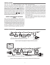
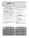
WIRING DIAGRAMS
L
R
C
24 VAC
120 VAC
Hot
SYSTEM
MONITOR
SWITCH
Neutral
THERMOSTAT
SYSTEM
G W2
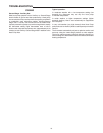
Figure 2. Typical wiring diagram for single transformer systems
TRANSFORMER
(Class II Current Limited)
Changeover
Relay*
YO/B
Compressor
Contactor
* Changeover Relay is energized in COOL when O/B switch is in the “O” position
Changeover Relay is energized in HEAT when O/B switch is in the “B” position
Aux/Emergency
Heat Relay
(Stage 2)
Fan
Relay
Optional
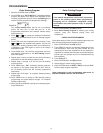
L
R
C
24 VAC
120 VAC
Hot
SYSTEM
MONITOR
SWITCH
Neutral
THERMOSTAT
SYSTEM
G W2
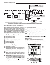
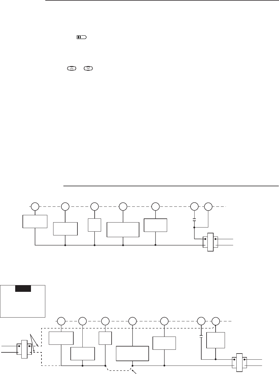
Figure 3. Typical wiring diagram for two transformer systems with NO safety circuits
TRANSFORMER
(Class II Current Limited)
Changeover
Relay*
YO/B
Compressor
Contactor
* Changeover Relay is energized in COOL when O/B switch is in the “O” position
Changeover Relay is energized in HEAT when O/B switch is in the “B” position
Aux/Emergency
Heat Relay
(Stage 2)
Fan
Relay
Optional
Limit or
Safety
Switches
TWO COMMONS MUST
BE JUMPERED TOGETHER!
HOT
NEUTRAL
120 VAC
24 VAC
CUT AND
TAPE OFF!
If safety circuits are in
only one of the systems,
remove the transformer
of the system with NO
safety circuits.
NOTE