


2
REMOVE OLD THERMOSTAT
1. Shut off electricity at the main fuse box until installation is
complete. Ensure that electrical power is disconnected.
2. Remove the front cover of the old thermostat. With wires
still attached, remove wall plate from the wall. If the
old thermostat has a wall mounting plate, remove the
thermostat and the wall mounting plate as an assembly.
3. Identify each wire attached to the old thermostat using
the labels enclosed with the new thermostat.
4. Disconnect the wires from old thermostat one at a time. DO
NOT LET WIRES FALL BACK INTO THE WALL.
5. Install new thermostat using the following procedures.
ATTENTION!
This product does not contain mercury. However, this product
may replace a unit which contains mercury.
Do not open mercury cells. If a cell becomes damaged, do
not touch any spilled mercury. Wearing nonabsorbent gloves,
take up the spilled mercury and place into a container which
can be sealed. If a cell becomes damaged, the unit should be
discarded.
Mercury must not be discarded in household trash. When the
unit this product is replacing is to be discarded, place in a
suitable container. Refer to www.white-rodgers.com for location
to send the product containing mercury.
ATTACH THERMOSTAT BASE TO WALL
1. Remove the packing material from the thermostat. Gently
pull the cover straight off the base. Forcing or prying on the
thermostat will cause damage to the unit.
2. Place base over hole in wall and mark mounting hole
locations on wall using base as a template (see Fig.1).
3. Move base out of the way. Drill mounting holes.
4. Push wires through opening in thermostat base.
5. Fasten base loosely to wall using two mounting screws.
Place a level against bottom of base, adjust until level,
and then tighten screws. (Leveling is for appearance only
and will not affect thermostat operation.) If you are using
existing mounting holes, or if holes drilled are too large and
do not allow you to tighten base snugly, use plastic screw
anchors to secure subbase.
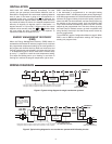
6. Connect wires to terminals on base using appropriate
wiring schematic (see fi gs. 2 through 4).
7. Push excess wire into wall and plug hole with a fi re-resistant
material (such as fi berglass insulation) to prevent drafts
from affecting thermostat operation.
O/B TERMINAL SWITCH SELECTION
The O/B switch on this thermostat is factory set to the “O”
position. This will accommodate the majority of heat pump
applications, which require the changeover relay to be
energized in COOL. If the thermostat you are replacing or the
heat pump being installed with this thermostat requires a “B”
terminal, to energize the changeover relay in HEAT, the O/B
switch must be moved to the “B” position.
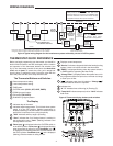
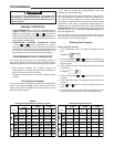
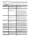
INSTALLATION
Mounting
Hole
Mounting
Hole
Opening
for wires
O/B
Switch
Battery
Door
Fan
Switch
HP-SS
Switch
Figure 1. Thermostat Base
HP-SS SWITCH AND FAN SWITCH
HP-SS Switch - If your system is a heat pump, the HP-SS
Switch must be set to HP (see Fig. 1). If your system is a
single stage, the switch must be set to SS. The switch setting
must agree with the system confi guration selected in the
confi guration menu.
Fan Switch - For Electric Heat, heat pump or any system that
requires the thermostat to turn on the blower on a call for heat
- place the FAN switch (Fig. 1) in the ON position. For Gas
Furnaces or Emergency Heat systems that have a fan control
to turn on the blower (independent of the thermostat) place
switch in the OFF position.
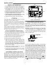
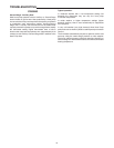
BATTERY LOCATION
Two “AA” alkaline batteries are installed in your thermostat
with a battery tag to prevent power drainage. Prior to use,
open the battery door and remove the battery tag. To open,
pull the battery door as shown by the arrow and lift open. The
two “AA” batteries will operate all functions or maintain time
and continuously display the temperature during a loss of AC
power. Installed batteries will also allow programming prior to
installation. To replace batteries, pull the battery door shown
by the arrow and lift open. Using the polarity indicated inside
the battery door, insert the batteries. To close the battery door,
swing the door down while pulling in the direction of arrow.
Once fully down, snap the door back into position.
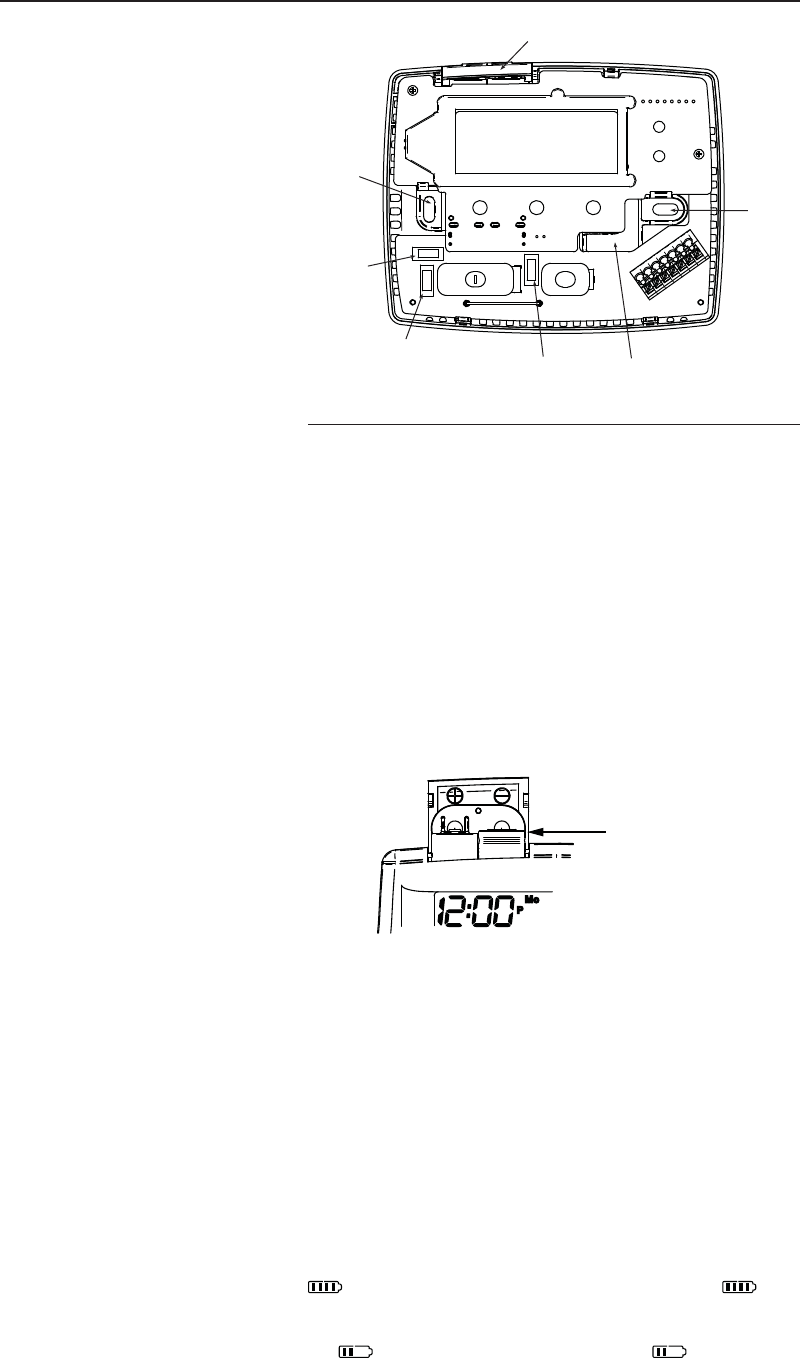
Thermostat can be powered by system AC power or Battery. If
is displayed, the thermostat is battery powered. If is not
displayed, thermostat is system powered with optional battery
back-up. When battery power remaining is approximately half,
the will be displayed. When “Change ” is displayed,
“AA” Alkaline Batteries