


GOLD CGa Gas-Fired Water Boiler — Boiler Manual
52
Part Number 550-101-009/0107
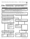
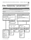
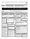
Troubleshooting — spark-pilot boilers11c
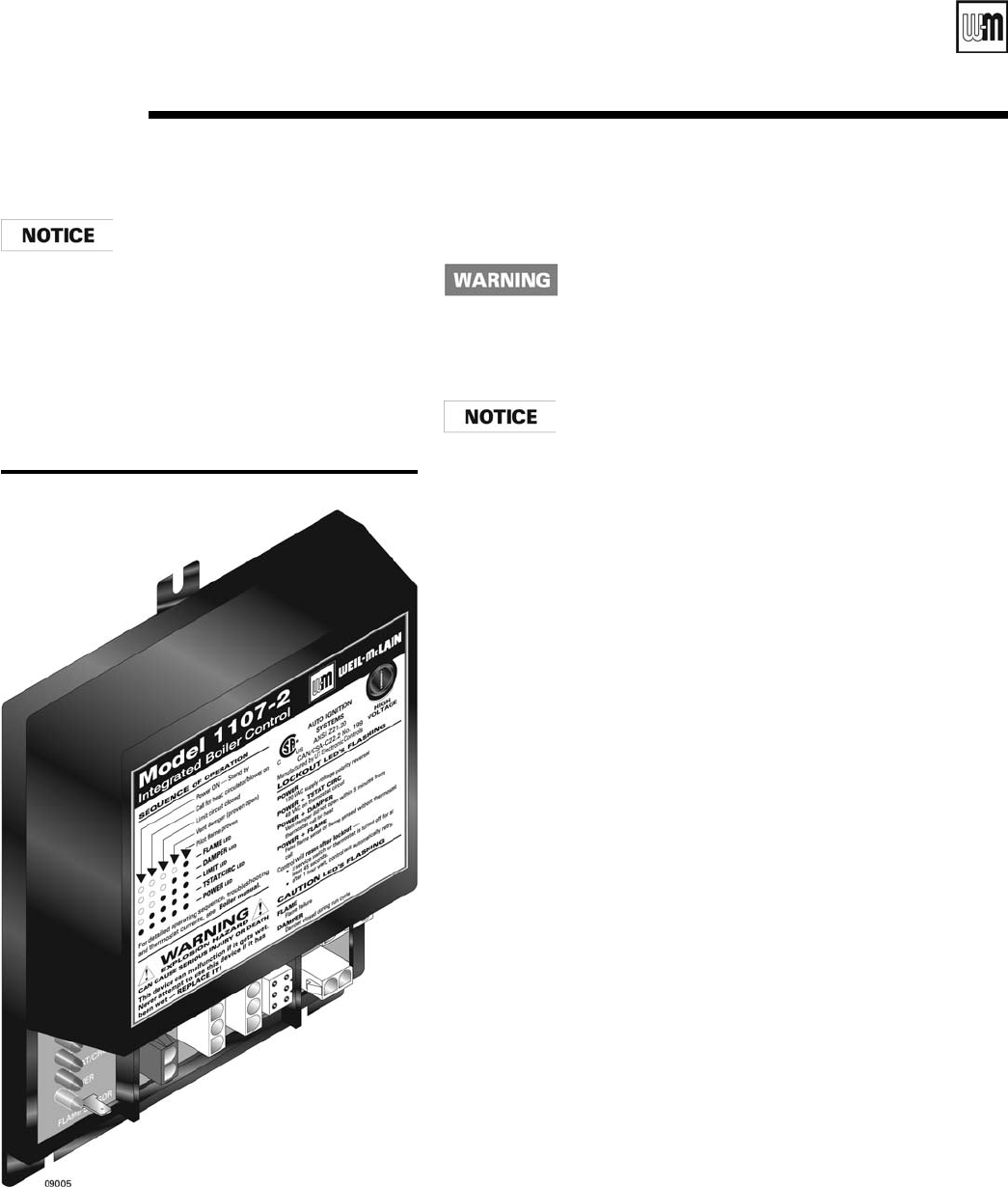
The information on this page and
pages 53 through 59 apply only to
spark-ignited pilot CGa boilers.
These boilers are equipped with an
ignition control module that has in-
dicator lights to show control status.
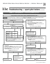
Charts 2 through 7, pages 54-59,
help you identify problems based
on indicator light conditions.
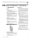
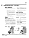
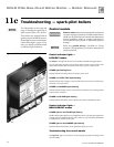
Figure 29 CGa Ignition control module
Control module
Solder or water splatter between plugs and circuit board
can cause improper operation of control module. Place a
shield over the boiler internal controls and components
during installation. Failure to comply could result in
severe personal injury, death or substantial property
damage.
Make sure ground wiring is installed per wiring
diagram. Good grounding is extremely important for
proper operation.
Control indicator lights —
LOCKOUT modes
See Charts 1 through 7 in this section for detailed troubleshooting procedures.
To reset control after a lockout, turn off power at the 120 VAC service switch or turn
down all thermostats. Wait 45 seconds. Then restore power or call for heat.
POWER light flashing alone
Usually indicates reversed polarity of 120 VAC power wires.
POWER and TSTAT CIRC lights flashing
Usually indicates stray voltage on external thermostat circuit wires (usually due to
miswired 3-wire zone valve).
POWER and DAMPER lights flashing
Usually indicates damper circuit is closed when it should not be, or damper failed
to close within 5 minutes.
POWER and FLAME lights flashing
Usually indicates false flame sense or flame sensed when it shouldn’t be there.
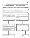
Control indicator lights —
NON-LOCKOUT modes
POWER light on and FLAME light flashing
Usually indicates pilot flame was not established within 15 seconds from application
of spark. Control will flash light, but will continue to cycle indefinitely until flame
is established or problem is corrected.
POWER light on and DAMPER light flashing
Usually indicates the damper circuit opened during the run cycle.
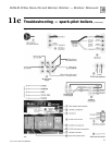
Troubleshooting the control module
See Figure 30 , page 53, for location of harness plug receptacles and plugs on the
control module.