


Part Number 550-101-009/0107
27
GOLD CGa Gas-Fired Water Boiler — Boiler Manual
Field wiring
For your safety, turn off electrical power supply at
service entrance panel before making any electrical
connections to avoid possible electric shock hazard.
Failure to do so can cause severe personal injury or
death.
Wiring must be N.E.C. Class 1.
If rollout thermal fuse element wire as supplied with
boiler must be replaced, type 200°C wire or equivalent
must be used. If other original wiring as supplied with
boiler must be replaced, use only type 105°C wire or
equivalent.
Boiler must be
electrically grounded as required by
National Electrical Code ANSI/NFPA 70-latest edi-
tion.
Installation must comply
with:
1. National Electrical Code and any other national,
state, provincial or local codes or regulations.
2. In Canada, CSA C22.1 Canadian Electrical Code
Part 1, and any local codes.
Wiring connections
Boiler is shipped with controls completely wired, except
spill switch and vent damper. Refer to wiring diagrams
shown on page 34 for standing pilot ignition boiler or
page 38 for spark-ignited pilot boiler.
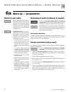
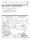
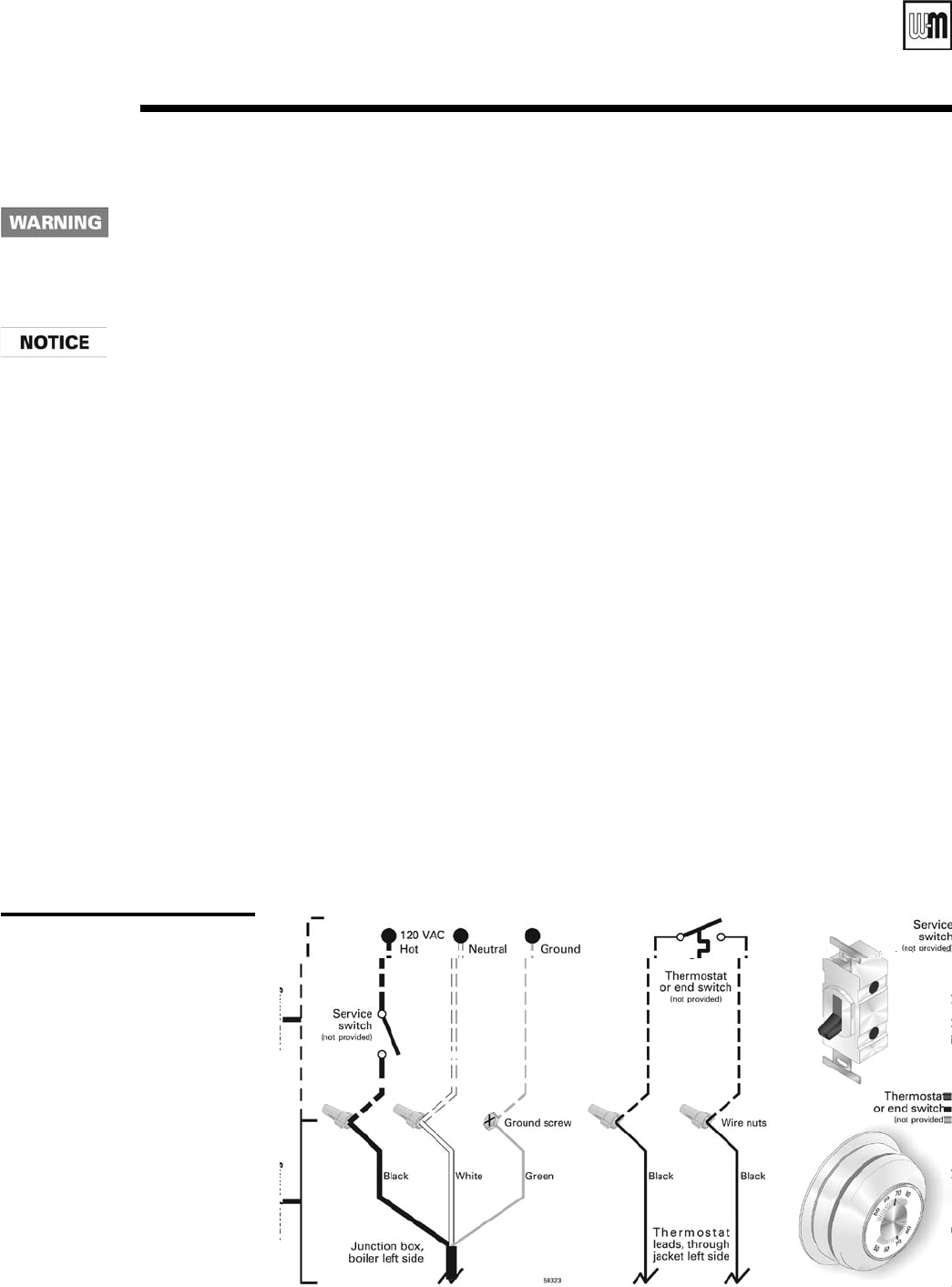
Figure 20
Field wiring connections —
service switch and thermostat
(or end switch) provided by
installer
5
Thermostat
1. Connect thermostat as shown on wiring diagram
on boiler.
2. Install on inside wall away from influences of drafts,
hot or cold water pipes, lighting fixtures, television,
sunrays or fireplaces.
3. If thermostat has a heat anticipator, set heat antici
-
pator in thermostat to match power requirements
of equipment connected to it. If connected directly
to boiler, set for 0.1 amps plus gas valve current.
See information on the wiring diagram shown in
Figure 25b, page 39. For other devices, refer to
manufacturer’s specifications. Wiring diagram on
boiler gives setting for control module and gas valve.
Also see instructions with thermostat.
Junction box (furnished)
1. Connect 120 VAC power wiring (Figure 20).
2. Fused disconnect or service switch (15 amp. recom
-
mended) may be mounted on this box. For those
installations with local codes which prohibit instal-
lation of fused disconnect or service switch on boiler,
install a 2 x 4 cover plate on the boiler junction box
and mount the service switch remotely as required
by the code.
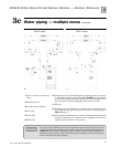
Wiring multiple zones
Refer to zone valve manufacturer’s literature for wiring
and application. A separate transformer is required to
power zone valves. Zoning with circulators requires a
relay for each circulator.