


GOLD CGa Gas-Fired Water Boiler — Boiler Manual
16
Part Number 550-101-009/0107
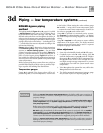
Water piping — general information3a
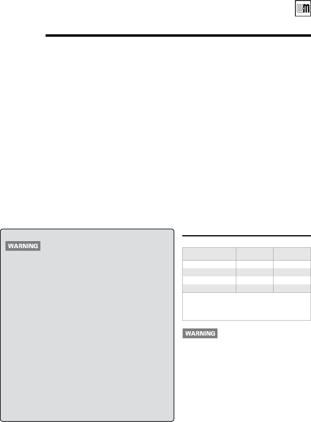
Boiler model To
system
From
system
CGa-25 ¾" ¾"
CGa-3, 4, 5 1" 1"
CGa-6, 7 1 ¼" 1 ¼"
CGa-8 1 ½" 1 ½"
Note: The boiler supply and return connections, the return/
drain tee and the supply/gauge tee supplied with the
boiler are 1¼” NPT. One of the circulator flanges sup-
plied with the boiler is 1¼”. The other circulator flange
is the size of the recommended system piping shown
above.
General piping information
If installation is to comply with ASME or Canadian requirements, an ad-
ditional high temperature limit is needed. Install control in supply piping
between boiler and isolation valve. Set second control to minimum 20°F
above setpoint of first control. Maximum allowable setpoint is 240°F. See
page 34 or 38, for wiring.
A low water cutoff device is required when boiler is installed above ra-
diation level or by certain state or local codes or insurance companies. Use
low water cutoff designed for water installations. Electrode probe-type is
recommended. Purchase and install in tee in supply piping above boiler.
Use backflow check valve in cold water supply as required by local
codes.
Pressure/temperature gauge
Install pressure/temperature gauge in tee on supply piping (as shown in
drawing on page 3).
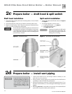
Relief valve
Install relief valve vertically in ¾” tapping on side of boiler. See Figure 9
or 10, page 17, and the tag attached to the relief valve for manufacturer’s
instructions.
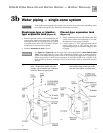
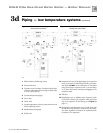
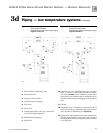
System water piping
See Figure 9 (diaphragm-type or bladder-type expan-
sion tank) or Figure 10 (closed-type expansion tank),
and Table 3 below, for near-boiler and single-zone
systems designed for return water at least 130°F.
See pages 18-19 to complete multiple-zone piping or
pages 20-25 to complete piping for radiant heating
systems or converted gravity systems (large-volume
systems originally designed for circulation by natural
convection rather than a pump). See page 25 for boilers
used with refrigeration systems.
Chillers or air handling units:
Install boiler such that —
• Chilled medium, if used, is piped in parallel with
heating boiler. Use appropriate valves to prevent
chilled medium from entering boiler. Consult
I=B=R Installation and Piping Guides.
• If boiler is connected to heating coils located in
air handling units where they can be exposed to
refrigerated air, use flow control valves or other au-
tomatic means to prevent gravity circulation during
cooling cycle. Circulation of cold water through the
boiler could result in damage to the heat exchanger,
causing possible severe personal injury, death or
substantial property damage.
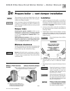
Circulator
The circulator is shipped loose (wiring pre-attached to
boiler) to allow you to locate it either in the return or
supply piping, as desired. See page 3 for a typical instal-
lation. Pipe the expansion tank to the suction side of the
circulator whenever possible. Install an air separator in
the supply piping. Connect the expansion tank to the air
separator only if the separator is on the suction side of
the circulator. Always install the system fill connection
at the same point as the expansion tank connection to
the system. Figures 9 and 10 show typical near-boiler
piping connections.
Table 3 Water pipe size (based on 20°F rise)
To avoid water damage or scalding due to relief valve
operation:
• Discharge line must be connected to relief valve outlet and run to a
safe place of disposal. Terminate the discharge line to eliminate
possibility of severe burns should the valve discharge.
• Discharge line must be as short as possible and be the same size as
the valve discharge connection throughout its entire length.
• Discharge line must pitch downward from the valve and terminate
at least 6” above the floor drain where any discharge will be clearly
visible.
• The discharge line shall terminate plain, not threaded, with a mate-
rial serviceable for temperatures of 375°F or greater.
• Do not pipe the discharge to any place where freezing could
occur.
• No shutoff valve shall be installed between the relief valve and boiler,
or in the discharge line. Do not plug or place any obstruction in the
discharge line.
• Failure to comply with the above guidelines could result in failure of
the relief valve to operate, resulting in possibility of severe personal
injury, death or substantial property damage.
• Test the operation of the valve after filling and pressurizing system
by lifting the lever. Make sure the valve discharges freely. If the valve
fails to operate correctly, replace it with a new relief valve.