


General piping information:
• If installation is to comply with ASME or
Canadian requirements, an additional high
temperature limit is needed. Install control in
supply piping between boiler and isolation valve.
Set control to a minimum of 20°F above set
point of combination control. Maximum
allowable set point is 220°F. Wire control as
shown on wiring diagram.
• Use a low water cutoff device when:
— Boiler is installed above radiation level.
— Required by certain state or local codes or
insurance companies.
Use low water cutoff designed for water
installations. Probe-type is recommended. Purchase
and install in tee in supply line above boiler.
• Use backflow check valve in cold water supply
as required by local codes.
• “A2” or “A3” tapping not recommended for
system supply piping. If “A2” or “A3” tapping
must be used, adequate air elimination method
must be provided.
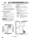
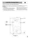
Install piping:
• See FIGURE 7 or 8 on page 13 and Water
Piping Size Table at right for near-boiler piping
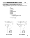
and single-zone piping. See page 14 to complete
multiple-zone piping or page 15 to complete
piping for systems operating below 140°F.
For multiple-boiler piping, refer to Weil-McLain’s
“Primary/Secondary Piping Guide."
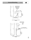
• Install relief valve vertically in “R” tapping
on back of boiler. See FIGURE 7 or 8 and also
refer to tag attached to relief valve for
manufacturer’s instructions.
Pipe relief valve discharge line
near floor close to floor drain to
eliminate potential of severe burns. Do not
pipe to any area where freezing could occur.
Do not plug, valve or place any obstruction in
discharge line.
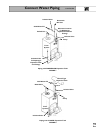
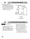
DIAPHRAGM expansion tank (FIGURE 7):
• Make sure expansion tank size will handle boiler
and system water volume and temperature. Tank
must be located near boiler before inlet to circulator.
See tank manufacturer’s instructions for details.
Undersized expansion tanks cause
system water to be lost from relief
valve and makeup water added through fill valve.
Eventual section failure can result.
• Install automatic air vent in “A2” tapping as
shown in FIGURE 7.
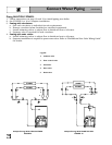
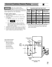
CLOSED expansion tank (FIGURE 8):
• Ensure expansion tank size will handle boiler
and system water volume and temperature.
Undersized expansion tanks cause
system water to be lost from relief
valve and makeup water added through fill valve.
Eventual section failure can result.
• Connect tank from “A2” tapping shown in
FIGURE 8 to expansion tank. Use
1
¼2" N.P.T.
piping. Pitch any horizontal piping up towards
tank 1 inch per 5 feet of piping.
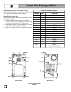
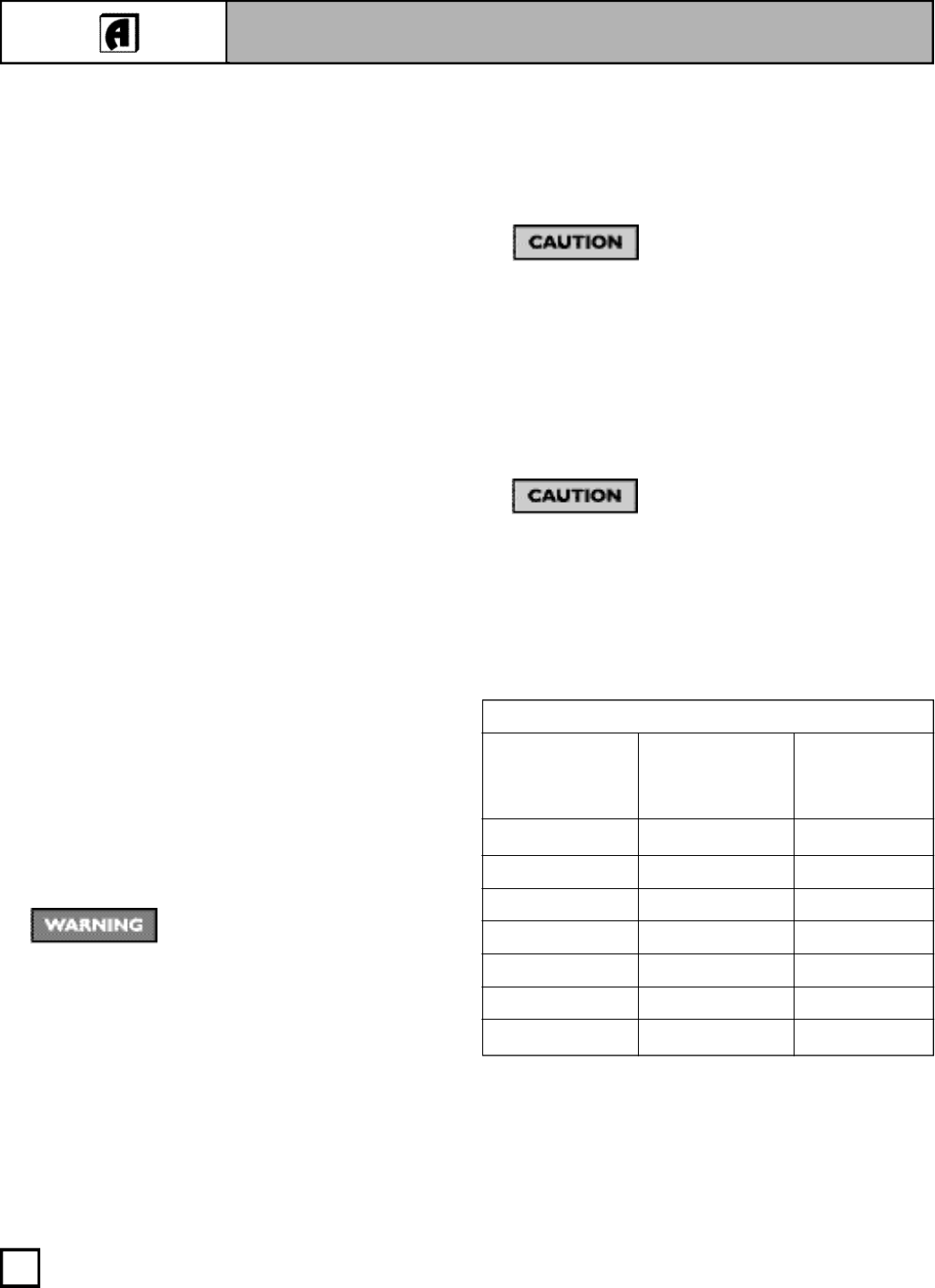
* All piping sizes based on 20°F temperature rise through boiler.
12
Connect Water Piping
WATER PIPING SIZE TABLE*
BOILER
MODEL TO FROM
NUMBER SYSTEM SYSTEM
SGO-3W 1¼" 1¼"
SGO-4W 1¼" 1¼"
SGO-5W 1½" 1½"
SGO-6W 1½" 1
1
¼2"
SGO-7W 1½" 1½"
SGO-8W 2" 2"
SGO-9W 2" 2"