


Above Floor Installation Guide
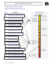
Part Number 650-000-221/0298
11
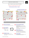
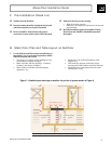
G. Mark Floor Plan and Tube Layout on Subfloor
1. Use the Tube Layout Plan to mark the following on
the subfloor. Use several colors if possible to define
different elements and circuits.
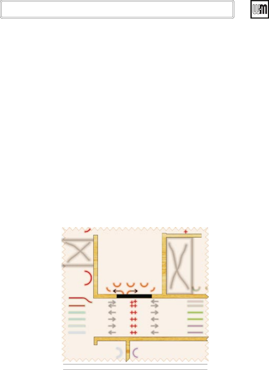
See Figure 7 for typical layout markings for the
system shown in Figure 6, page 6.
Mark wall lines and door openings (if interior
framing is not already installed).
Mark outlines of kitchen and bath cabinets,
appliances, etc.
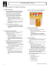
F. Pre-Installation Check List
q Subfloor must be installed.
q Interior framing should be completed, but drywall
and finish carpentry not in place if possible.
q Review AlumiPex Trade Guides with general
contractor to ensure other trades will be informed.
q Make provision for pressure testing:
• Water if no freeze concern.
• Otherwise, air compressor and hoses for air test and
pressurization.
q Read this installation guide, the AlumiPex Fitting
Instructions and AlumiPex Manifold Instructions
thoroughly.
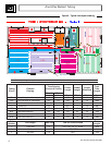
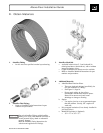
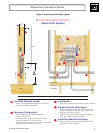
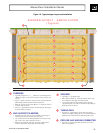
Return Bends (typical)
Counters and Avoidance
Areas (Typical)
Counters and Avoidance
Areas (Typical)
Return Bends (typical)
Manifold
Penetration Holes
(Typical)
Penetration Hole (Typical)
Leader Routing
(typical)
Leader Routing
(typical)
This drawing is conceptual only. Consult heating system designer for actual job details.
Figure 7 - Possible layout markings on subfloor for portion of system shown in Figure 6
Mark areas to be avoided (fireplaces, toilet
flanges, etc.).
Then mark key portions of the tube layout,
showing tube bend locations and flow direction.
• Mark locations of penetration holes in rooms
and hallways, if any.