WM 550-141-996/1105 Page 9
RWB 6104WMNX R1005
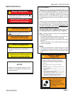
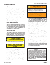
Warning – By-pass Plug in
2 Pipe System
The burner pump is shipped without the by-pass plug
installed. You must install this plug on two-pipe oil
systems. If the unit is a one-pipe oil system DO NOT
install the plug in the pump.
Failure to comply could cause pump
seal failure, oil leakage and the
potential for a fire and injury hazard.
S110
!
Prepare the Burner
General
In most cases, the burner is ready to mount to the
appliance. There can be situations where the burn-
er needs to be reconfi gured to perform properly in
the appliance. Review the appliance manufactur-
er’s specifi cations prior to installing to determine if
any modifi cation is required to properly confi gure
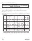
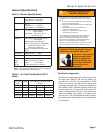
the burner. Refer to Table 1.
Instruction on how to perform the following burner
preparation tasks can be found in the Professional
Maintenance section.
Remove / install burner nozzle
Check head/air adjusting plate
Mount Burner on Appliance
Verify that the air tube installed on the burner pro-
vides the correct insertion depth. Bolt the burner
to the appliance using the factory-welded fl ange.
Note that the end of the tube will extend into the
chamber on UO-4 and UO-5 boilers.
Connect Fuel Lines
The burner is supplied with either a one-stage
pump or a two-stage pump based on the oil supply
system requirements. Consult the instructions pro-
vided with the pump for installation specifi cations.
•
•
•
•
•
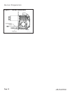
When installing a two-pipe system, remove the
1/16” pipe by-pass plug from plastic bag attached
to fuel unit. Remove ¼” plug from return port. In-
sert and tighten the by-pass plug. Attach return
and inlet lines. Start burner. Air bleeding is au-
tomatic. Open the easy fl ow air bleed valve for a
faster bleed, if desired. The return line should ter-
minate approximately 3-4” above supply line inlet.
Failure to do this may introduce air into the system
and could result in loss of prime.
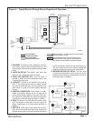
Wiring Connection Diagram
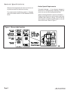
Burner wiring performed at jobsite: Refer to Figure
3, for typical burner interconnect wiring, Burner
wiring may vary, depending on the burner specifi -
cation. Refer to Figure 4 for burner wiring details.
All wiring must be in accordance with the latest re-
vision of National Electric Code NFPA 70 and all
local codes and regulations.
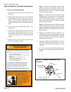
The R7184 primary control with valve-on delay and
burner motor-off delay, shown in Figure 4, requires
a constant 120 volt AC power source supplied to
the black wire on the control. The red wire goes
to the appliance limit circuit. Please note that other
control manufacturers may use different wire colors
for power and limit connections.
•
Caution–Oil Supply
Pressure Control Required
The oil supply inlet pressure to the fuel unit cannot exceed
3 psi. Insure that a pressure-limiting device is installed in
accordance with the latest edition of the NFPA 31.
Damage to Pump Seal could cause
possible oil leakage and potential
fire hazard.
S109
!
Burner Preparation
When installing a one-pipe system, connect the
inlet line to the pump inlet. Start the burner. Ar-
range the primary burner control for continuous op-
eration during priming by pressing the control reset
button during prepurge. Open the bleed valve one
turn counterclockwise. Prime the system until all
air bubbles have disappeared. Tighten the bleed
valve securely.
The fuel pump may be installed with gravity feed
or lift. The maximum allowable lift for a single pipe
installation is 8 ft.
NOTICE
The NX burner has a reduced diameter air tube,
precision-designed air throttle cup and combus-
tion head for improved performance. This de-
sign provides very accurate control of the air/fuel
ratio, but the light reaching the cad cell through
small holes in these components is limited. Be-
cause of this, the average cad cell resistance
may be higher than conventional burners
with larger openings.


