


Page 12 WM 550-141-996/1105
RWB 6104WMNX R1005
Start the Burner and Set Combustion
Start-up and Initial Settings
Open the shutoff valves in the oil supply line to
the burner.
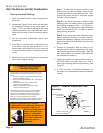
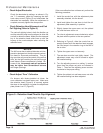
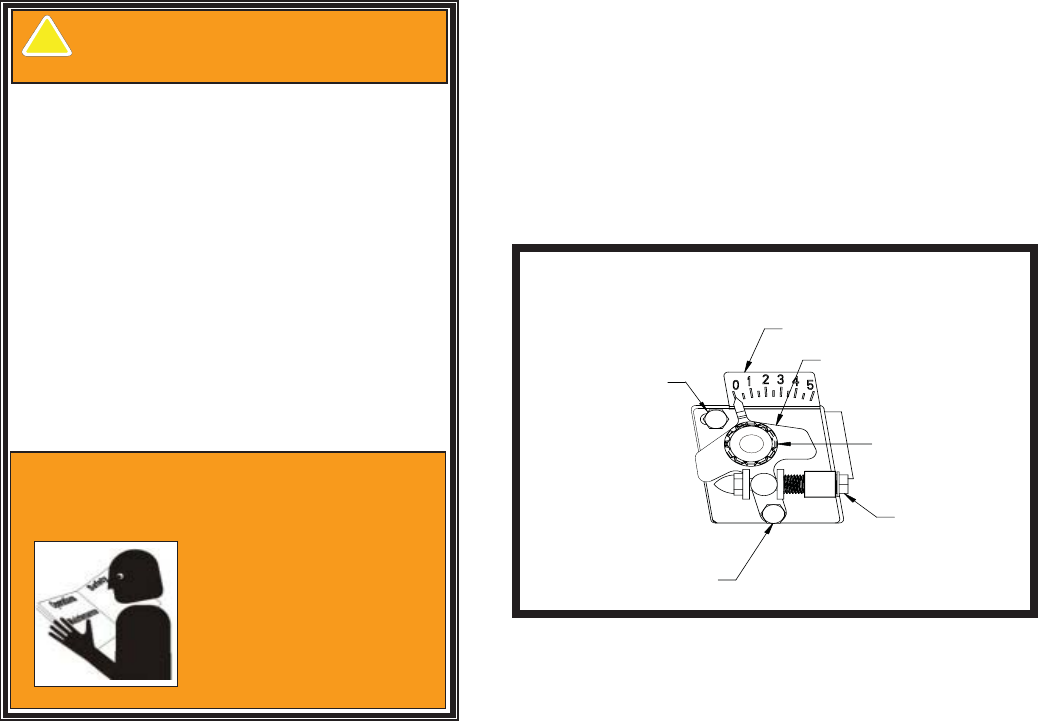
Referencing Figure 5 verify and/or set the Head/
Air Adjustment Pointer to the value shown in
Table 1. This is an initial air setting for the pump
bleeding procedure only. Calibrated test instru-
ments must be used for the fi nal head/air adjust-
ment.
Set the thermostat substantially above room
temperature.
Close the line voltage switch to start the burner.
If the burner does not start within the 3 to 10
second safety start check timing, you may have
to reset the safety switch on the burner primary
control.
Bleed the air from the fuel pump as soon as the
burner motor begins rotating.
•
1.
2.
3.
4.
5.
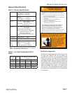
Warning–Professional
Service Required
This equipment must be installed, adjusted and put into
operation only by a qualified individual or service agency
that is:
x Licensed or certified to install and provide technical
service to oil heating systems.
x Experienced with all applicable codes, standards and
ordinances
x Responsible for the correct installation and
commission of this equipment
x Skilled in the adjustment of oil burners using
combustion test instruments.
The installation must strictly comply with all applicable
codes, authorities having jurisdiction and the latest
revision of the National Fire Protection Association
Standard for the Installation of Oil-Burning Equipment,
NFPA 31 (or CSA B139 and B140 in Canada).
Regulation by these authorities take precedence over the
general instructions provided in this installation manual.
S105
Read and understand the manual
supplied with this equipment. Incorrect
installation, adjustment, and use of
this burner may result in
severe personal injury
death, or substantial
property damage from
fire, carbon monoxide
poisoning, soot or
ex
p
losion.
!
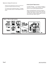
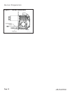
Figure 5. – Head/air Adjustment Plate
Assembly
Upper Acorn Nut
(Lock Zero
Calibration)
Lower Acorn Nut
(Lock Air Setting)
Scale
Pointer
Splined
Nut
Adjustment
Nut
SK9667
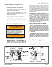
Start the Burner
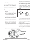
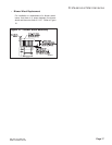
Step 1: To bleed the fuel pump, attach a clear
plastic hose over the vent fi tting. Loosen the fi t-
ting and catch the oil in an empty container. Tight-
en the fi tting when all the air has been purged
from the oil supply system.
Step 2: If the burner locks-out on safety during
bleeding, reset the safety switch and complete
the bleeding procedure. Note — For R7184 pri-
mary controls, see Technician’s Quick Reference
Guide, part number 61351 or 61465, for special
pump priming sequence.
Step 3: If the burner stops after a fl ame is estab-
lished, additional bleeding is probably required.
Repeat the bleeding procedure until the pump is
primed and a fl ame is established when the vent
fi tting is closed.
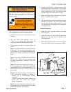
Prepare for combustion tests by drilling a
1/4
”
sampling hole in the fl ue pipe between the appli-
ance and the barometric draft regulator. Seal this
hole when testing is complete. (See appliance
manufacturer for location.)
Loosen the splined nut approximately one turn.
(DO NOT loosen the upper acorn nut. This is
used only for setting the zero adjustment.) (See
Figure 5.)
A 5/16” nut driver or fl at blade screwdriver can
be used to turn the adjustment screw for head/air
setting.
6.
7.
8.