


Page 14 WM 550-141-996/1105
RWB 6104WMNX R1005
Warning–Professional
Service Required
This equipment must be installed, adjusted and put into
operation only by a qualified individual or service agency
that is:
x Licensed or certified to install and provide technical
service to oil heating systems.
x Experienced with all applicable codes, standards and
ordinances
x Responsible for the correct installation and
commission of this equipment
x Skilled in the adjustment of oil burners using
combustion test instruments.
The installation must strictly comply with all applicable
codes, authorities having jurisdiction and the latest
revision of the National Fire Protection Association
Standard for the Installation of Oil-Burning Equipment,
NFPA 31 (or CSA B139 and B140 in Canada).
Regulation by these authorities take precedence over the
general instructions provided in this installation manual.
S105
Read and understand the manual
supplied with this equipment. Incorrect
installation, adjustment, and use of
this burner may result in
severe personal injury
death, or substantial
property damage from
fire, carbon monoxide
poisoning, soot or
ex
p
losion.
!
Professional Maintenance
Trained Service Technician’s Regular
Maintenance
While performing routine maintenance check the
following.
Replace the oil supply line fi lter. The line fi lter car-
tridge must be replaced to avoid contamination of
the fuel pump and nozzle.
Inspect the oil supply system. All fi ttings should
be tight and leak-free. The supply lines should be
free of water, sludge and other restrictions.
Remove and clean the pump strainer if applica-
ble.
Replace the used nozzle with a new nozzle per
appliance manufacturer’s specifi cations.
Clean and inspect the electrodes for damage, re-
placing any that are cracked or chipped.
Check electrode tip settings. Replace electrodes
if tips are rounded.
Inspect the igniter spring contacts.
Clean the cad cell grid surface, if necessary.
Make sure Low Firing Rate Baffl e is in place if
required for the burner application. Omitting the
baffl e can result in unacceptable burner combus-
tion.
Inspect all gaskets. Replace any that are dam-
aged or would fail to seal adequately.
Clean the blower wheel, air inlet, air guide, reten-
tion head, throttle plate and throttle ring of any lint
or foreign material.
Check motor current. The amp draw should not
exceed the nameplate rating by more than 10%.
Check all wiring for secure connections or insula-
tion breaks.
Check the pump pressure and cutoff function.
Check primary control safety lockout timing.
Check ignition system for proper operation.
Inspect the vent system and chimney for soot ac-
cumulation or other restriction.
Clean the appliance thoroughly according to the
manufacturer’s recommendations.
Check the burner performance. Refer to the sec-
tion “Set combustion with test instruments”.
It is good practice to keep a record of the service
performed and the combustion test results.
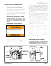
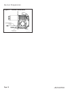
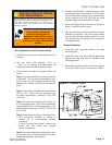
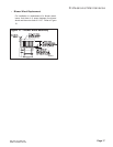
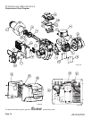
Removing Nozzle Line for Service (Refer-
ence the Replacement Parts drawing.)
Before proceeding, turn off the main power switch
to the burner.
Remove the burner cover by loosening the four
thumb screws (two on each side of burner).
•
•
•
•
•
•
•
•
•
•
•
•
•
•
•
•
•
•
•
•
1.
2.
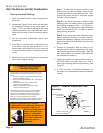
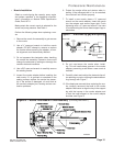
Disconnect the copper connector tube assembly
from the nozzle line bulkhead fi tting.
Loosen the two screws securing the igniter re-
taining clips and rotate both clips to release the
igniter baseplate. The igniter should pop up and
be supported by the prop spring.
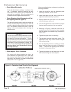
Loosen the two screws securing the rear door.
Swing the door to the right and down
Loosen the splined nut.
Remove the nozzle line electrode and head as-
sembly from the burner by drawing it straight
back and out the rear door opening. The adjust-
ment mechanism is still attached. Be careful not
to damage the electrodes or insulators while han-
dling.
To replace the nozzle assembly, reverse the
above procedure.
3.
4.
5.
6.
7.
8.