


Page 16 WM 550-141-996/1105
RWB 6104WMNX R1005
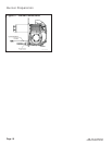
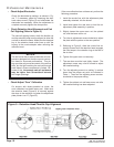
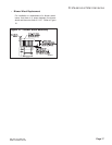
Check/Adjust Electrodes
Check the electrode tip settings, as shown in Fig-
ure 7. If necessary, adjust by loosening the elec-
trode clamp screw (Figure 8) and slide/rotate the
electrodes as necessary. When the adjustment is
complete, securely tighten the clamp screw.
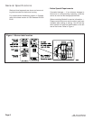
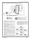
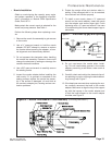
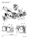
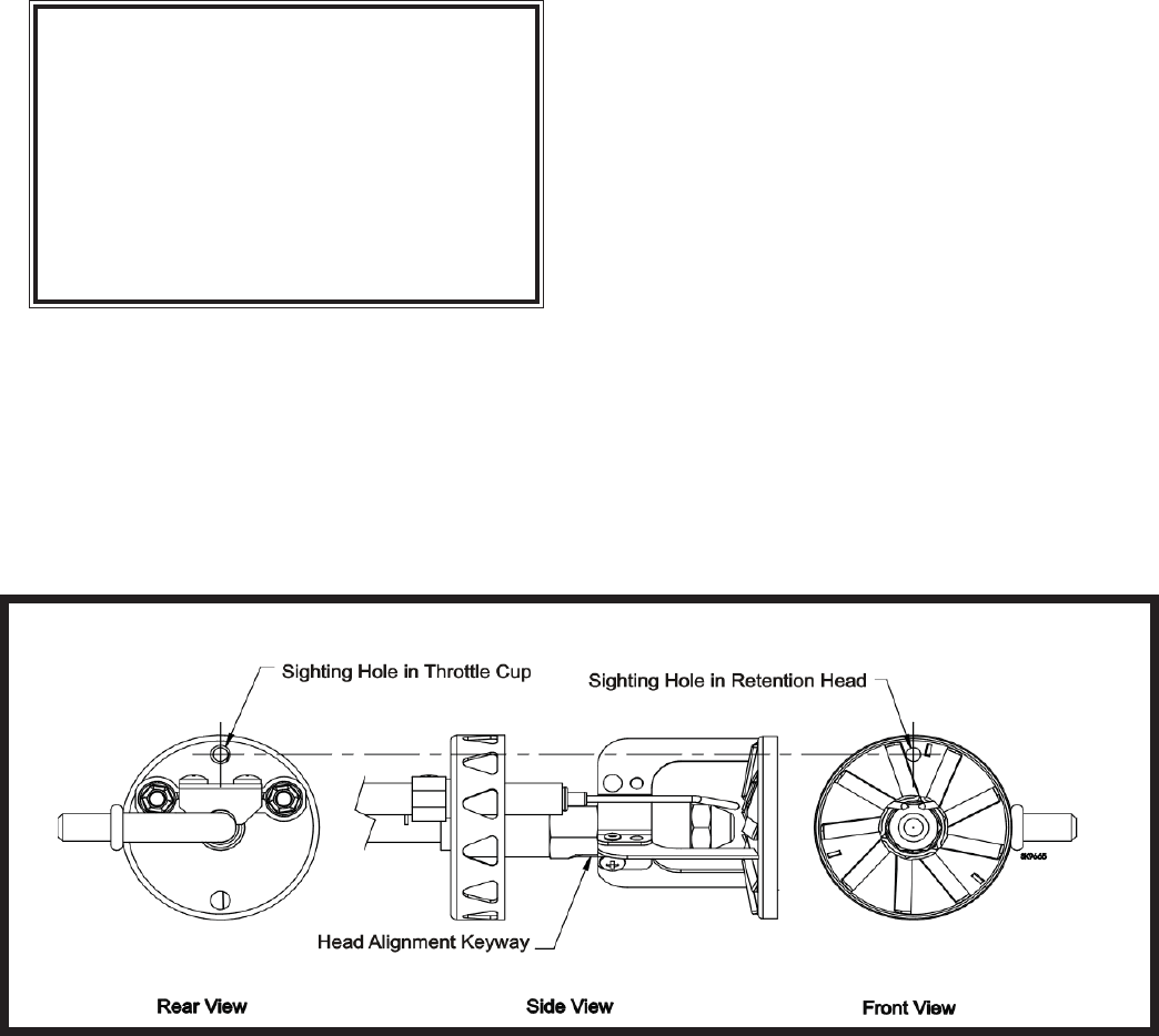
Check Retention Head Alignment and Cad
Cell Sighting (Refer to Figure 9.)
The cad cell sighting holes in both the throttle cup
and the retention head must be aligned to allow the
cad cell to detect the fl ame. Make sure the stamped
key in the retention head collar lines up with the
keyway in the nozzle adapter when mounting the
retention head.
•
•
If the zero calibration has not been set, perform the
following procedure:
Install the nozzle line, with the adjustment plate
assembly attached, into the burner.
Install and tighten the rear door to hold the air
adjustment plate assembly in position.
Slightly loosen the upper acorn nut, the splined
nut, and the lower acorn nut.
Turn the air adjustment screw clockwise to adjust
the plate with the pointer to the zero position.
Referring to Figure 8, slide the nozzle line as-
sembly forward until the retention head engages
the fi xed stops in the retention ring at the end of
the air tube.
Tighten the upper acorn nut securely.
The rear door must be kept tightly closed. The
adjustment screw may now be turned to adjust
the head/air setting.
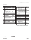
Turn the adjusting screw to a setting ½ number
lower than the proper set point as indicated in
Table 1. Then turn the adjusting screw counter-
clockwise to the proper setting.
Tighten the splined nut and lower acorn nut after
the head/air setting has been adjusted.
1.
2.
3.
4.
5.
6.
7.
8.
9.
Professional Maintenance
SK9665
Figure 9 – Retention Head/Throttle Cup Alignment
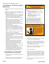
NOTICE
The NX burner has a reduced diameter air tube,
precision-designed air throttle cup and combus-
tion head for improved performance. This de-
sign provides very accurate control of the air/fuel
ratio, but the light reaching the cad cell through
small holes in these components is limited. Be-
cause of this, the average cad cell resistance
may be higher than conventional burners
with larger openings.
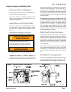
Check/Adjust “Zero” Calibration
On burners with factory-installed air tubes, the
zero calibration has been factory set. Make sure
the retention head (Figure 8) is securely against
the stops in the retention ring when the adjustment
plate pointer is at “0” (Figure 5).
•