AQUA PLUS indirect-fired water heaters — Product Manual
Boiler-side piping
(continued)
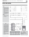
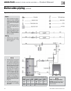
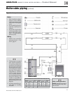
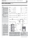
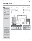
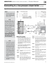
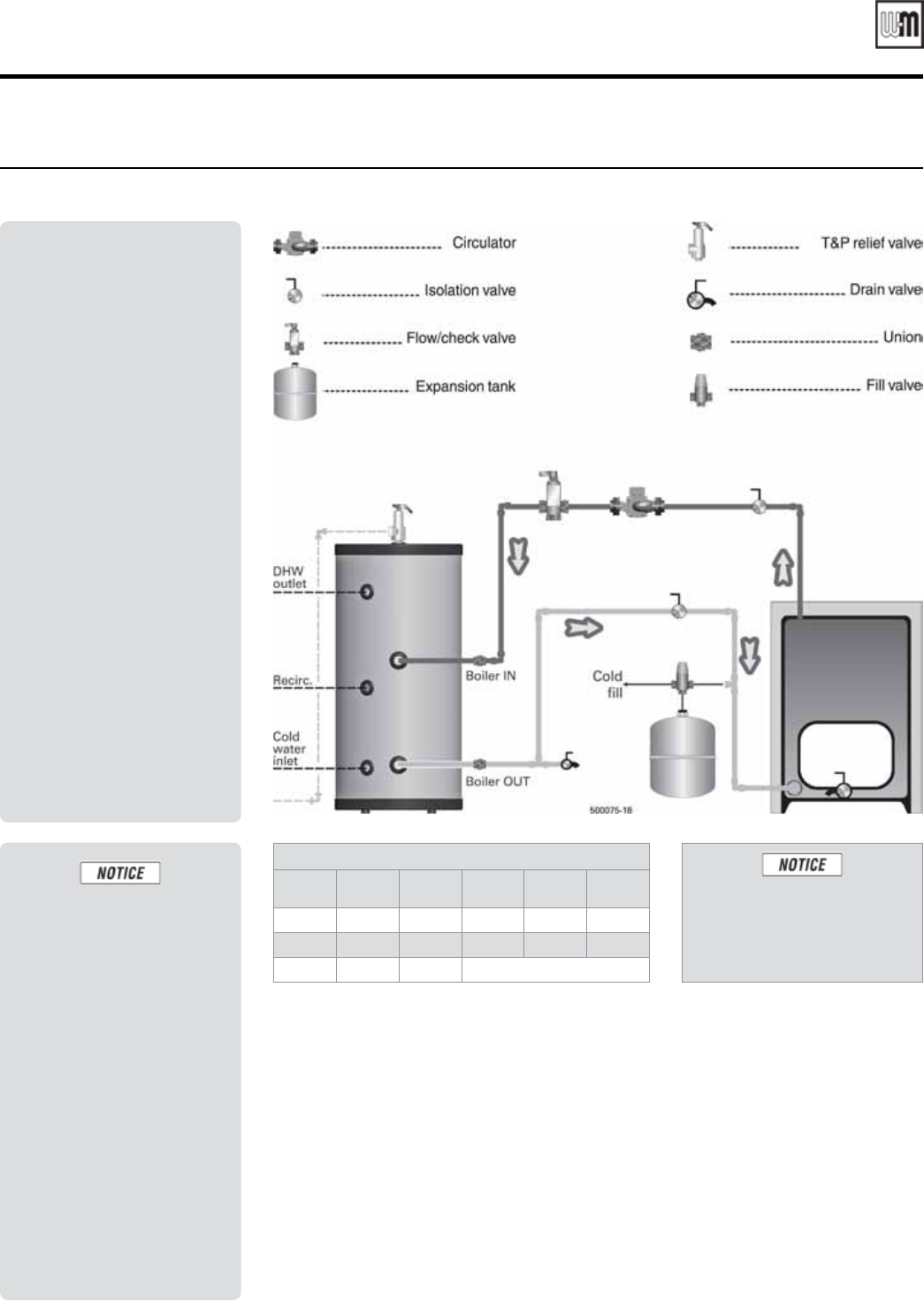
Figure 11 Dedicated single-boiler piping
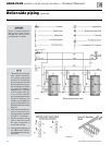
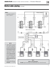
Notes
• Place circulators at begin-
nings of zones. Placing
them at the ends of zones
could result in heating idle
zones.
• Size manifold piping for
total flow of all zone cir-
culators.
• Locate flow / check valves
as close as possible to water
heater boiler side connec-
tions — to reduce heat loss
between cycles.
Wiring
• Connect water heater ther-
mostat wires to boiler’s
T-T terminals or heat de-
mand connection.
1. This drawing is conceptual
only. It shows representa-
tive piping components
and layout. Weil-McLain
does not represent that this
drawing meets any partic-
ular mechanical or build-
ing codes. The installer is
responsible for inclusion
of all required safety de-
vices, or other miscella-
neous piping hardware not
shown on drawing. The
installer is responsible for
proper sizing / selection of
all hardware shown on this
diagram.
2. See boiler manual for spe-
cific details on installing
the boiler.
GV90+ or Ultra gas boilers:
DO NOT apply the drawings in
this manual. Refer only to the
boiler manual.
Recommended flow rate and minimum boiler-side pipe size
Heater
model
GPM
Pipe
size
Heater
model
GPM
Pipe
size
35
8 1”
85
14 1¼” *
45
8 1”
105
14 1¼” *
55
8 1”
Requires 1¼”x1” reducers at water heater
Part number GL-E223-ADOC 0311
15


