


AQUA PLUS indirect-fired water heaters — Product Manual
Connecting to a low-pressure steam boiler
(continued)
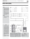
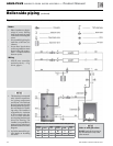
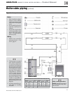
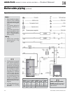
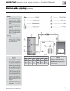
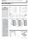
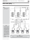
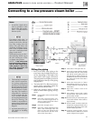
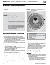
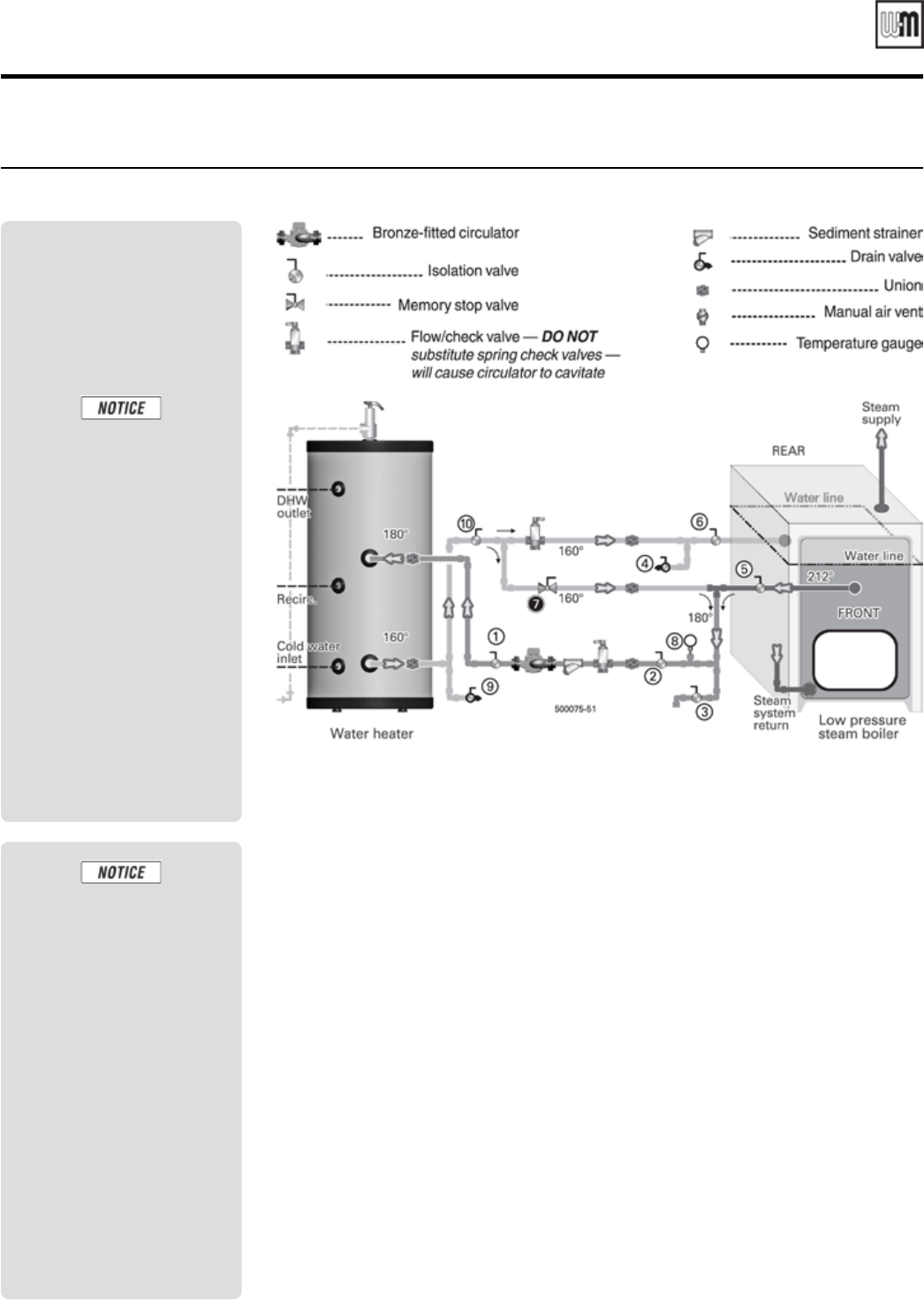
Figure 16 Low pressure steam boiler application — Domestic water heating using water pumped from steam boiler
Notes
• Locate flow / check valve as
close as possible to water
heater boiler side connec-
tions — to reduce heat loss
between cycles.
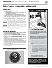
Use memory stop valve 7 to
blend some of the water re-
turning to the boiler with the
hot water coming from the
boiler. This will reduce the
possibility of flashing (cavita-
tion) in the circulator. Slowly
open valve 7 until temperature
gauge 8 reads 200°F.
Set the memory stop on valve 7
after adjusting. Attach a tag to
the valve warning no to close
or change valve position.
NOTE —
If the boiler water
level should drop below ei-
ther the water heater boiler
water supply or return line,
the filling procedure will
have to be repeated.
1. This drawing is conceptual
only. It shows representa-
tive piping components
and layout. Weil-McLain
does not represent that this
drawing meets any partic-
ular mechanical or build-
ing codes. The installer is
responsible for inclusion
of all required safety de-
vices, or other miscella-
neous piping hardware not
shown on drawing. The
installer is responsible for
proper sizing / selection of
all hardware shown on this
diagram.
2. See boiler manual for spe-
cific details on installing
the boiler.
Filling the piping
1. Parts of the boiler water piping to the
water heater may be higher than the wa-
ter line, depending on the height of the
water heater boiler supply connection.
The piping must be air tight to prevent air
from pocketing at the top of the piping,
stopping flow.
2. The boiler MUST be filled and ready to
operate before proceeding. Follow the
boiler manual to fill the boiler.
3. Follow the procedure below to fill the
boiler-to-water heater piping. See Fig-
ure 16.
Step 1 Close isolation valves 5 and 6 to isolate
the boiler.
Step 2 Close valve 3 and open valve 4. Con-
nect a cold water supply hose to
valve 3. Connect a hose from valve 4
to a drainable location.
Step 3 Close valve 10. Open valve 7.
Step 4 Open valve 3. Water will flow through
valve 7 and out through valve 4 to
drain. Let water run until all air has
been removed from the line. Close
valve 4. Then close valve 3.
Step 5 Close valve 7. Then open valve 10.
Step 6 Open valve 3. Water will flow through
the circulator line, the water heater
coil and the return piping, then out
through valve 4 to drain. Let water run
until all air has been removed from the
line. Close valve 4. Then close valve 3.
Remove hoses.
Step 7 Follow the instructions in “Water
heater filling and start-up,” page 23,
to fill the domestic water side of the
water heater.
Step 8 Open valve 7 about ¼ turn for an
initial setting.
Step 9 Open isolation valves 5and 6. Make
sure the boiler water level is correct
per the boiler manual.
Step 10 Start the boiler per instructions given
in the boiler manual. Allow boiler to
begin steaming.
Step 11 Start the DHW circulator. Watch the
temperature at gauge 8. Adjust valve 7
until gauge 8 reads about 180°F with
system at steady operation.
Step 12 Continue checking under varying
DHW demand conditions to ensure
system will operate as required.
Part number GL-E223-ADOC 0311
19