


AQUA PLUS indirect-fired water heaters — Product Manual
Boiler-side wiring and controls
Electrical shock hazard — Can cause severe personal
injury, death or substantial property damage. Disconnect
power before installing and / or servicing.
Wiring requirements
1. All wiring must be a minimum of 18 gauge and installed in accordance
with:
• U.S.A. — National Electrical Code and any other national, state or
local code requirements having jurisdiction.
• Canada — CSA C22.1 Canadian Electrical Code Part 1 and any
other national, provincial and local code requirements having
jurisdiction.
2. If original wire as supplied with appliance must be replaced, Type 90°
C or its equivalent must be used.
3. Refer to control component instructions packed with boiler for ap-
plication information.
4. An optional service switch may be installed in water heater electri-
cal circuit. This switch would only shut off the water heater, not the
home heating system. Do not shut off water heater if there is a chance
of freezing.
5. All electrical contacts are shown with no power applied — off-the-
shelf condition.
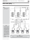
Circulators
1. Size priority relay for total amp draw of all circulators.
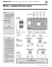
Zone Valves
1. Size transformer for maximum load of all zone valves.
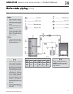
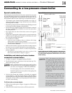
Wiring to the water heater
1. Field connections to the water heater thermostat are for 24 VAC only,
connecting to the two-pole terminal block shown in Figure 17.
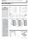
Wiring options
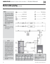
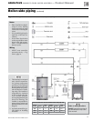
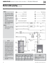
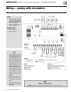
1. This manual shows wiring only for use of Weil-McLain WMCR Cir-
culator Zone Controller or Weil-McLain WMZV Zone Valve Zone
Controller.
2. Other wiring methods may be acceptable and are left to the installer.
Use domestic priority
1. When possible, set controls to provide domestic
priority — that is, on a call for domestic water
the control switches from space heating to DHW
only.
2. Domestic priority ensures the fastest possible re-
sponse to the DHW call for heat.
3. The smaller the water heater, the greater the need
for rapid response.
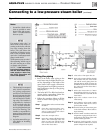
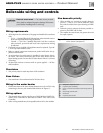
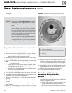
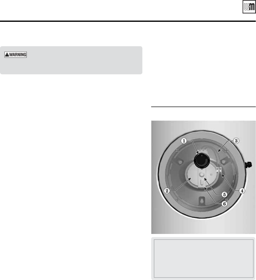
Figure 17 Inspection hatch assembly (hatch
cover shown transparent)
1 Temperature adjustment knob
2 Inspection plate (handhole)
3 Factory wires from thermostat to field wiring terminal
block
4 Field wiring terminal block
5 M8 hex nut
6 Inspection plate bracket
Part number GL-E223-ADOC 0311
20