


• Installation • Start-Up • Maintenance • Parts
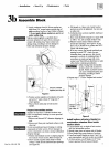
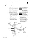
Connect Steam Boiler Piping
6a
General steam piping information:
• Hartford Loop piping arrangement and wet
return are required for steam boilers.
• Maintain 24-inch minimum from waterline to
bottom of header (56-1/4" from bottom of
section).
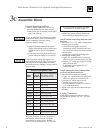
• When using condensate receiver, feed pump
must be energized by boiler-mounted pump
controller.
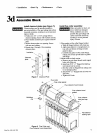
Install piping:
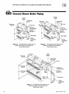
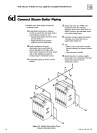
Install piping as shown on page 16 for single
boilers, page 18 for multiple boilers.
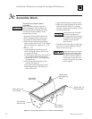
Improperly piped systems or
undersized piping can contribute
to erratic boiler operation and
possible boiler or system
damage. Piping system must be
installed as shown, using pipe
sizes shown. Consult local Weil-
McLain distributor or sales office
before installing alternate piping.
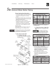
1. Connect supply and return piping:
a. See table below and:
1)Size forced condensate return piping by
pump.
2)Size gravity condensate return same as
equalizer “J” pipe size.
b. Install system drain valve in lowest part of
return piping close to boiler. ASME size
requirements are shown in Table, page 13.
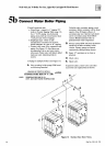
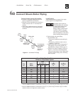
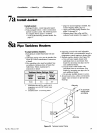
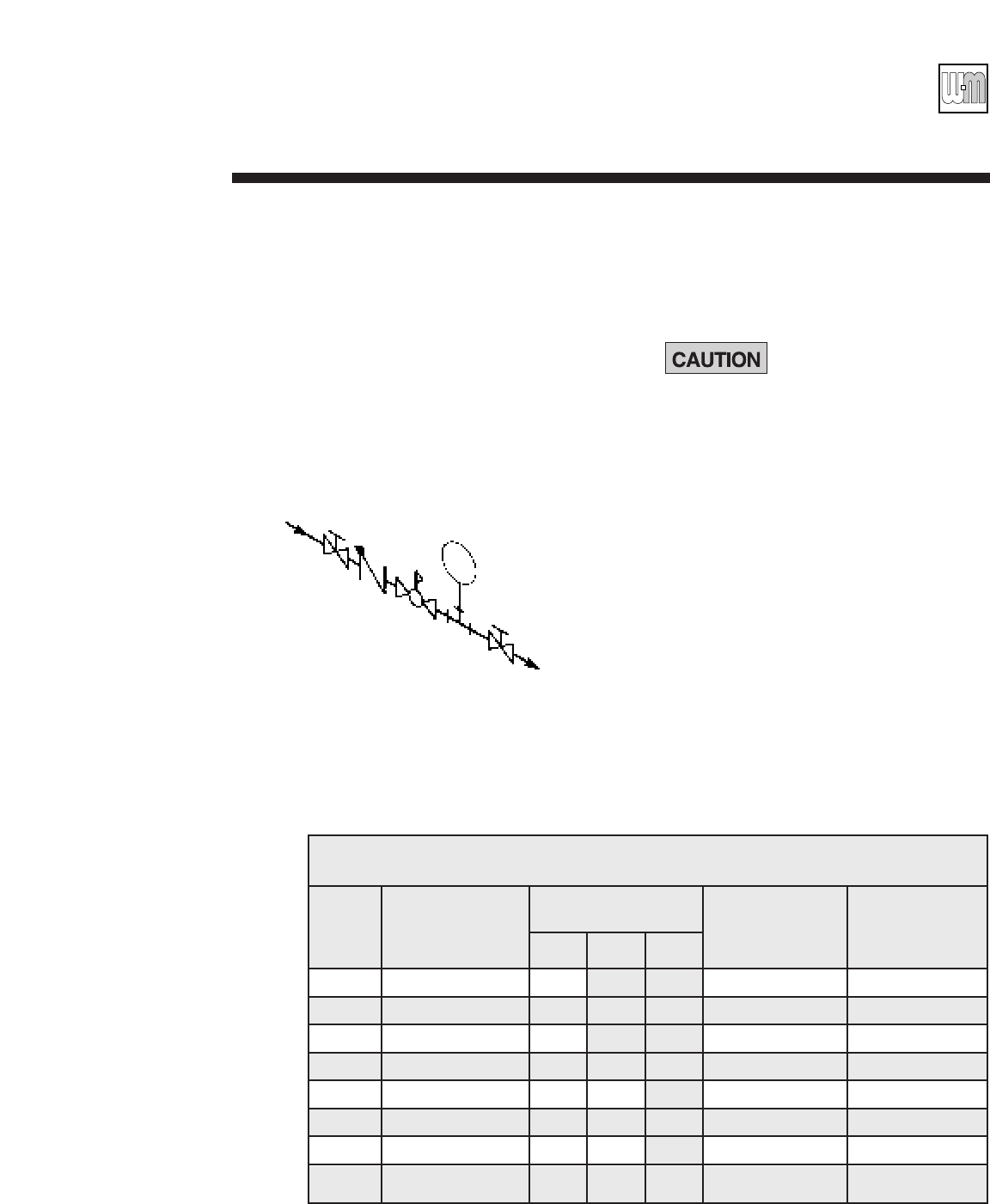
c. Connect cold water fill piping as shown in
Figure 14. Also shown are recommended
valves and water meter, if used. Water meter
will detect added makeup water, indicating
leaks in system.
Part No. 550-141-705
15
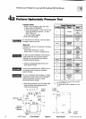
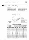
* Based on ASHRAE Handbook recommendations, allowing 1/2 oz. pressure drop per 100 feet of pipe for dry return.
**Based on ASHRAE Handbook recommendations, allowing 2 oz. pressure drop per 100 feet of pipe at 3.5 PSIG.
Maintain minimum 24" height from waterline to header.
Steam Boiler Pipe Size Table
Based on 2-Pipe Steam System
*Riser * *
Pipe Size - In. H J
Fig. Boiler Header Equalizer
No. Model A B C In. In.
15 378 3 3 2
15 478 4 4 2
15 578 4 4 2-1/2
16 678 3 3 4 2-1/2
16 778 4 4 4 2-1/2
16 878 4 4 4 3
16 978 4 4 6 3
17 1078-1278 4 4 4 6 3
Cold
water fill
Manual
isolation
valve
Pressure
reducing valve
(when used)
Manual
isolation
valve
Water meter
Check
valve
To condensate
return piping or
condensate
receiver
(see fig. 18,
page 17)
Figure 14 Cold Water Fill Piping