


Close clearance installation:
Substitute these instructions for corresponding
material in manual. All other procedures and
practices must remain the same.
Recommended service and minimum clearances
shown on page 4 should be used where possible.
Where closer clearances are required:
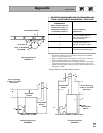
• Top of boiler — If less than 24" available,
provide removable surface to allow for cleaning
boiler flueways.
• Right or left side — Minimum 2 inches.
• Front — Minimum 2 inches from burner.
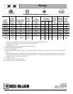
• Doublewall flue pipe to combustible surface —
as listed in Table on page 27 and FIGURES 19
through 21.
Jacket cap must be in place on
boiler to avoid requiring an 18"
minimum clearance from back or top of boiler to
combustible material. Flue pipe clearances must
take precedence over jacket clearances.
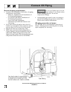
1. Install boiler using clearances described at left.
2. Install barometric control 18-20 inches from
boiler in breeching.
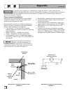
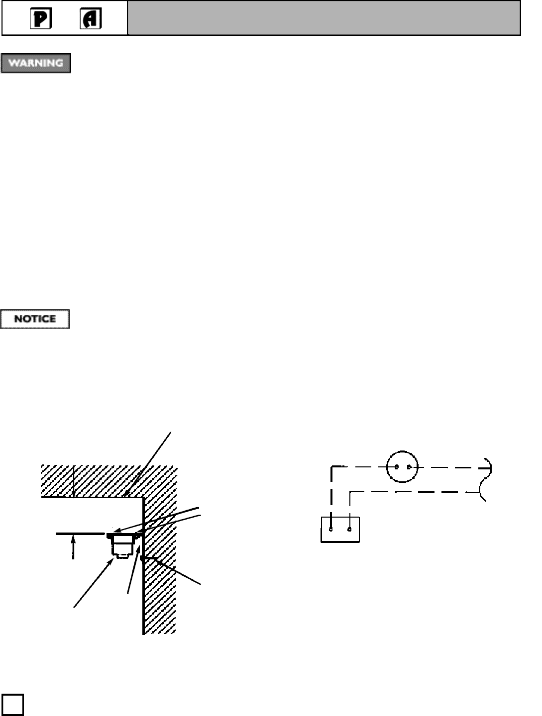
3. Attach manual reset temperature switch near
upper surface of enclosed area. See FIGURE 17.
4. Wire switch in series with thermostat. See
FIGURE 18.
5. Provide two combustion/ventilation openings
when installing in confined space. Size opening
140 sq. in. (1000 Btu) per 1 GPH input. Locate
openings near top and bottom of enclosed space.
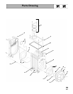
Appendix
CONTINUED
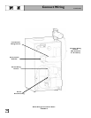
To provide close clearances as described in pages 26 and 27, Close Clearance Kit,
W-M Part No. 386-500-050, must be obtained and installed as described below. Failure to
use kit or install as described can result in a fire hazard, causing severe personal injury, death or
substantial property damage.
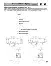
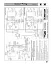
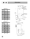
Manual Reset Temperature Switch Location
FIGURE 17
Manual Reset Temperature Switch Wiring
FIGURE 18
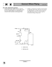
Area Above Boiler
Combustible
Surface
Manual Reset
Temperature Switch
Thermostat
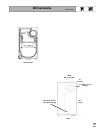
#6 x ½" Phil.
Sht. Mtl. Screw
#10 x ½" Phil.
Sht. Mtl. Screw
Bracket
1 to 5
inches
Manual
Reset
Temperature
Switch
44156
26