


Perform hydrostatic pressure test:
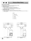
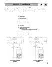
1. See FIGURE 4 and Control Tapping Table
below to install:
a. Boiler drain.
b. Water pressure gauge (test only). Be sure
gauge can handle test pressure.
c. Air vent in upper “N” tapping.
d. Plugs in remaining tappings.
2. Fill boiler. Vent all air. Pressure test boiler at 1
times working pressure. For boilers split and
reassembled, test between 75 and 85 psig.
Do not leave boiler unattended.
Cold water fill could expand and
damage cast iron, resulting in severe personal
injury, death or substantial property damage.
3. Check for maintained gauge pressure for more
than 10 minutes. Visually check for leaks if
gauge pressure drops.
4. Drain boiler. Repair leaks if found.
Do not use petroleum-based
compounds to repair leaks.
Damage to system components can result,
causing property damage.
5. Re-test boiler after repairing leaks.
6. Remove pressure gauge, air vent and plugs
from tappings used for controls.
7. Visually check:
a. Sealing rope placement.
b. Metal-to-metal contact around port openings.
c. Flue collector hood seal.
d. Burner mounting door seal.
Obtain gas-tight seal to prevent
possible flue gas leakage and
carbon monoxide emissions, which can lead to
severe personal injury or death.
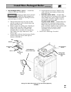
Install jacket (sizes 7 through 9 only):
Before installing jacket, remove burner mounting
door. See jacket instructions for details.
Install boiler controls:
See Control Tapping Table and FIGURES 4 and 5
to install controls.
1. Install limit control. If not furnished, use high
limit with maximum 220°F setting.
2. Affix CP number label(s) on jacket front panel.
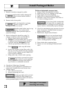
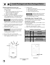
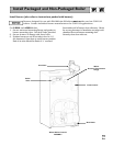
CONTROL TAPPING TABLE
LOCATION SIZE FUNCTION
B1 1½" Return Piping
B2 1
½
"
Alternate Return Piping
for A/B WGO
C 1½" Supply Piping
E3 ¾" Pressure-Temperature Gauge
H ¾" Drain Valve
L ¾" High Limit Control
N
½"
Air Vent or
Expansion Tank Piping
R1 ¾" Relief Valve
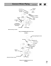
Install Packaged and Non-Packaged Boiler
Control Tapping Location
FIGURE 4
Back SectionFront Section
E3
R1
C
L
B1
H
B2
N
10