


Part number 550-110-260/0508
10
GOLD CGs Gas-Fired Water Boiler — Boiler Manual
Prepare boiler location — air openings1e
Special considerations
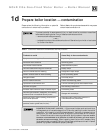
Tight construction
ANSI Z223.1 defines unusually tight construction
where:
1. Walls and ceilings exposed to the outside atmo-
sphere have a continuous water vapor retarder with
a rating of 1 perm or less with openings gasketed,
and . . .
2. Weather-stripping has been added on openable
windows and doors, and . . .
3. Caulking or sealants are applied to areas such as
joints around windows and door frames, between
sole plates and fl oors, between wall-ceiling joints,
between wall panels, at penetrations for plumbing,
electrical, and gas lines, and in other openings.
For buildings with such construction, provide air open-
ings into the building from outside, sized per the ap-
propriate case in Figure 3 if appliances are to use inside
air for combustion and ventilation.
Exhaust fans and air movers
The appliance space must never be under a negative
pressure unless all appliances are installed as direct vent.
Always provide air openings sized not only to the dimen-
sions required for the fi ring rate of all appliances, but
also to handle the air movement rate of the exhaust fans
or air movers using air from the building or space.
Motorized air dampers
If the air openings are fi tted with motorized dampers,
electrically interlock the damper to:
• Prevent the boiler from fi ring if the damper is not
fully open.
• Shut the boiler down should the damper close dur-
ing boiler operation.
To accomplish this interlock, wire an isolated contact
(proving the damper open) in series with the thermo-
stat input to the boiler. The boiler will not start if this
contact is open, and will shut down should it open
during operation.
Combustion air options
✷
Using inside air — direct exhaust vent
The CGs boiler can use inside air if no contaminants are present in the
boiler space. If contaminants are likely to be present, install the CGs boiler
as a direct vent appliance, using the appropriate vent supplement and the
instructions in this manual.
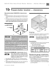
Using outside air — direct vent
Combustion air can be ducted directly from outside to the CGs boiler
air intake fi tting. This method is defi ned as direct vent (also referred to
as sealed combustion). Refer to the appropriate vent supplement and the
instructions in this manual. Two options are available: sidewall or vertical
direct vent. Each requires a special vent component kit.
Sizing air openings
✷
Air openings provide for ventilation (as well as combustion air) to prevent
overheating of the boiler controls and boiler space. Air is also needed for
other appliances located in the same space.
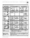
Use
Figure 3, page 11, selecting the appropriate installation conditions.
Note that the sizing given in Figure 3 applies only to CGs installations with
clearances no smaller than shown in Figure 1, page 7 of this manual.
For smaller clearances, regardless of how the air openings are arranged, two
openings providing free area of 1 square inch per 1,000 Btuh input of all
appliances in the space are required.
Air openings must be sized to handle all appliances and
air movers (exhaust fans, etc.) using the air supply.
The sizing given in Figure 3 is based on the National Fuel Gas Code, ANSI
Z223.1, allowing adequate air opening for gravity-vented gas appliances
(Category I). The CGs boiler is rated Category III or IV (pressurized vent),
and has different requirements for combustion and ventilation air, refl ected
by the special sizing instructions given in Figure 3. The air openings recom-
mended in Figure 3 will allow adequate ventilation and
combustion air provided the boiler room is not sub-
jected to negative pressure due to exhaust fans or other
mechanical ventilation devices. Refer to the National
Fuel Gas Code for dealing with other conditions.
Louver allowance
The free area of openings means the area after reduc-
tion for any installed louvers or grilles
. Be sure to
consider this reduction when sizing the air openings.
Combustion air opening location and sizing
requirements depend on the clearances around
the boiler.
Check the boiler placement compared to
Figure 1, page 7.
If all clearances are at least equal to Figure 1,
page 7
, apply the sizing and placement of openings
given on pages 10 and 11.
If ANY clearance is less than Figure 1, page 7,
you must provide air openings sized and located
as shown in Figure 2, page 7. DO NOT apply the
sizing and location information shown on page 10
or 11. The Figure 2 air openings are required even if
the boiler is direct vented (outside air piped to the
boiler air intake as described in this manual). These
openings ensure adequate air circulation around the
boiler for cooling, even if the boiler does not use
inside air for combustion.
✷