


Part number 550-110-260/0200
49
Boiler Manual
continued
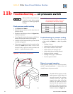
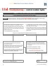
• ▲TURN OFF POWER▲ to boiler
at service switch or breaker.
• Remove air inlet box cover (see
Figure 27, page 54 for location).
• Verify inlet gas pressure at gas
valve:
Natural gas — 5.0" w.c. min/14.0"
w.c. max
Propane — 11.0" w.c. min/14.0"
w.c. max
Is gas present at gas valve inlet and
within above range?
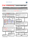
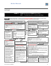
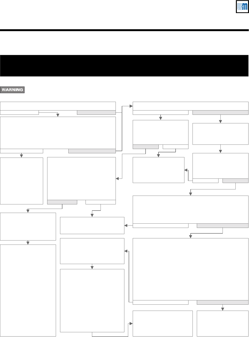
CHART 5 — FLAME light flashing and POWER light on steady
ALSO — Troubleshooting failure to establish main flame
Electrical shock hazard — Wherever you see ▲TURN OFF POWER▲, follow the instructions. Failure to follow
instructions could result in severe personal injury, death or substantial property damage.
No Yes
• Is pilot flame visible through inspection port?• Are main manual shutoff valve and boiler gas valve open?
No Yes
• ▲ TURN OFF POWER▲ to boiler at service switch or breaker.
• Open main manual shutoff valve and boiler gas valve (per
Lighting instructions in this manual). Wait at least 45
seconds.
• Turn on power at service switch or breaker. Allow boiler to
cycle.
Does
FLAME
light flash now?
No Yes
• Boiler should be in
normal operating
sequence.
• Observe operation
until thermostat is
satisfied and blower
has completed its
post-purge cycle.
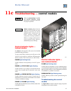
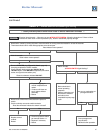
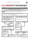
• Make sure ground wire
terminal is securely fastened
to control module mounting
screw.
• Check the voltage across
terminals "C" and "A" of the
gas valve (see Table G,
page 33).
Is 24 VAC present there?
NoYes
• Check the voltage across
terminals "B" and "A" (see
Table G, page 33) of the
gas valve.
Is 24 VAC present there?
No Yes
No
Yes
• Contact gas supplier to correct
pressure or gas supply.
• If the wiring from the
control module to gas
valve is intact, replace the
control module.
• Retest.
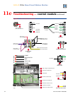
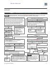
• ▲ TURN OFF POWER▲ to boiler at service switch or breaker.
• Check flame signal — Detach sense lead from igntion control
(
Figure 25, item 8, page 44
).
• Connect negative lead of MICROAMMETER to control sense
terminal (
Figure 25, item 8, page 44
). Connect positive lead of
MICROAMMETER to sense wire.
• DISCONNECT red wire connected to terminal "B" (see Table
G, page 33) of the gas valve.
• Turn on power to boiler and allow to cycle. As soon as pilot is
burning, the MICROAMMETER should read at least 1.0
microamp.
Is flame signal at least 1.0 microamp?
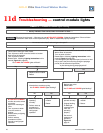
No Yes
• If the wiring from the
control module to gas
valve is intact, replace the
control module and retest.
• Verify inlet gas pressure at gas valve:
Natural gas — 5.0" w.c. min/14.0" w.c. max
Propane — 11.0" w.c. min/14.0" w.c. max
Is gas present at gas valve inlet and within above range?
No
Yes
• ▲ TURN OFF POWER▲ to
boiler at service switch or
breaker.
• Remove air inlet box top
(see Figure 27, page 54 for
location).
• Verify pilot gas line is not
kinked, obstructed or damaged
and is correctly attached to
pilot and gas valve.
• Verify pilot ignition electrode,
electrode ceramic and spark
lead wire from control are in
good condition. Spark gap
should be approximately 1/8".
• Correct any above problems,
replacing pilot if burner or
wiring is damaged.
• Reinstall air box top to operate
boiler for retest after any
changes or corrections.
• If none of the above corrects
problem, then replace the
control module, reinstall air box
top, and retest.
• Verify pilot burner is securely
attached to pilot bracket, bracket is
securely attached to cross tie, and
there is no corrosion on the parts
which would affect the ground path
for flame sense.
• Verify that pilot flame rod, flame rod
ceramic and lead wire from control
module to flame rod are in good
condition.
• Correct any above problems,
replacing pilot if burner or wiring is
damaged.
• If none of the previous steps
(including replacing pilot)
corrects problem, then replace
the control module, reinstall air
box cover and retest.