


Please Do Not Return This Product To The Store. Contact your local Wayne-Dalton dealer. To find your local Wayne-Dalton dealer,
refer to your local yellow pages business listings or go to the Find a Dealer section online at www.Wayne-Dalton.com
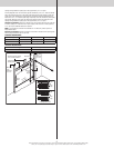
Vertical
track
assembly
Jamb
bracket
Flag
angle
Flag angle lag screw locations
5/16” x 1-5/8”
Lag screws
Bottom
section
Track
rollers
12R FA
3/8” to 5/8”
Spacing
Bottom section
Vertical track
15R FA 15R QI12R QI
Floor
Track roller
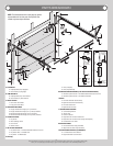
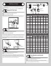
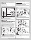
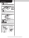
Stacking Sections
Tools: Power drill,7/16” Socket driver
8
NOTE: The sections can be identified by the graduation of the factory installed end hinges.
The smallest graduated end hinge on section should be stacked on top of the bottom section,
with each graduated end hinge increasing as the sections are stacked, see Parts Breakdown
on page 2.
NOTE: Make sure graduated end and center hinges are flipped down, when stacking another
section on top.
NOTE: Larger doors will use long stem track rollers with double graduated end hinges.
Place track rollers into graduated end hinges of remaining sections.
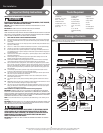
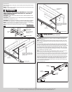
With assistance, lift second section and guide the track rollers into the vertical tracks. Lower
section until it is seated against bottom section. Align vertical marks in the upper alignment
sticker, with the lower alignment sticker on right hand side, on the back of door. Keep sec-
tions aligned and fasten center hinge(s) first; then end hinges last using 1/4”-14 x 5/8” self
tapping screws.
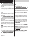
NOTE: To prevent center hinge leaf(s) from rotating, first secure the top middle hole of the
center hinge leaf with one 1/4” – 14 x 5/8” self-tapping screw then secure the other two
holes.
NOTE: Larger doors with double graduated end hinges, fasten both hinges to connect the
sections using 1/4” - 14 x 5/8” self-tapping screws.
Repeat same process for other sections, except top section.
IMPORTANT: PUSH & HOLD THE HINGE LEAFS SECURELY AGAINST THE SECTIONS WHILE
SECURING WITH 1/4”-14 X 5/8” SELF TAPPING SCREWS. THERE SHOULD BE NO GAP
BETWEEN THE HINGE LEAFS AND THE SECTIONS.
Lock section
Vertical
tracks
Alignment
sticker
Alignment
sticker
Center
hinge(s)
Left graduated end hinge
with short stem track roller
Left double graduated
end hinge with long
stem track roller
Right graduated end hinge
with short stem track roller
Right double graduated
end hinge with long
stem track roller
1/4”-14 x 5/8” Self tapping screw locations
Secure top
middle
hole first
P/N # 327985 NEW 9-04-06P/N # 327985 NEW 9-04-06
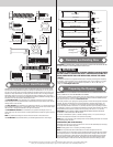
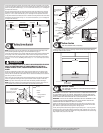
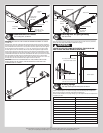
Top Fixtures
Tools: Power drill, 7/16” Socket driver
9
Remove, but retain (2-4) 1/4”- 14 x 7/8” self drilling screws from the right side of the strut,
allowing enough room to slide the top fixture between the section and the strut.
Slide the top fixture assembly between the strut and section. Align the edge of the top fixture
parallel to the top section edge. Secure the top fixture and strut to the top section with (3)
1/4”- 20 x 7/8” self drilling screws through the upper and lower slots of the top fixture. Finish
re-attaching the strut using the 1/4”- 20 x 7/8” self drilling screws removed previously. Insert
short stem track roller into top fixture. Repeat for left hand side.
Top fixture
base
Short stem
track roller
Strut
End cap
Top
section
(3) 1/4”-20 x 7/8”
Self drilling screws
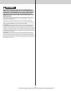
Drawbar Operator Bracket
Tools: Power drill, 7/16” Socket driver
10
NOTE: If you’re installing a drawbar operator, the drawbar operator bracket must be mounted
and secured prior to installing top section.
IMPORTANT: WHEN CONNECTING A DRAWBAR OPERATOR TYPE GARAGE DOOR OPENER
TO THIS DOOR, A WAYNE-DALTON OPERATOR/ DRAWBAR OPERATOR BRACKET MUST
BE SECURELY ATTACHED TO THE TOP SECTION OF THE DOOR, ALONG WITH ANY STRUT
PROVIDED WITH THE DOOR. THE INSTALLATION OF THE DRAWBAR OPERATOR MUST BE AC-
CORDING TO MANUFACTURER’S INSTRUCTIONS AND FORCE SETTINGS MUST BE ADJUSTED
PROPERLY.
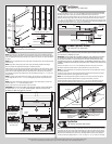
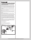
Remove, but retain (4-6) 1/4”-20 x 7/8” self drilling screws from the center of the strut,
allowing the drawbar operator bracket to slide between the section and the strut.
NOTE: For retro fit applications, the drawbar operator bracket must be aligned with an exist-
ing drawbar operator.
Locate the center of the top section and slide drawbar operator bracket under strut till the
drawbar operator bracket is seated against the strut flange.
NOTE: Prior to fastening drawbar operator bracket to top section, ensure the top edge of
drawbar operator bracket is aligned with the top edge of the section, as shown.
Attach the drawbar operator bracket using (8) 1/4” – 20 x 11/16” self drilling screws (as
shown). Finish re-attaching the strut using the self tapping screws removed previously.
(8) 1/4” - 20 x 11/16”
Self-drilling screws
Drawbar operator
bracket in place
under strut
Top section
Strut
Drawbar
operator bracket
Strut
Top section
1/4” - 20 x 7/8”
Self-drilling screws
Top Section
Tools: Hammer, Step ladder, Tape measure
11
Place the top section in the opening. Temporarily secure the top section by driving a nail into
the header near the center of the door and bending it over the top section. Now, flip up the
graduated end hinge and center hinge leaves, hold tight against section, and fasten center
hinges first and end hinges last (refer to step, Stacking Sections). Vertical track alignment
is critical. Position flag angle between 1-11/16” (43 mm) to 1-3/4” (44 mm) from the edge
8