


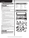
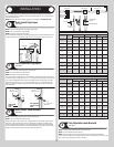


Please Do Not Return This Product To The Store. Contact your local Wayne-Dalton dealer. To find your local Wayne-Dalton dealer,
refer to your local yellow pages business listings or go to the Find a Dealer section online at www.Wayne-Dalton.com
horizontal track.
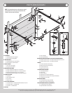
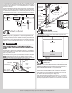
Attach rear back hangs to ceiling joist or other structurally sound framing members. Brace
rear back hangs.
NOTE: If an idrive
®
opener is installed, position horizontal tracks one hole above level when
securing it to the rear back hangs.
WARNING WARNING
KEEP HORIZONTAL TRACKS PARALLEL AND WITHIN 3/4” TO 7/8” MAXI-
MUM OF DOOR EDGE, OTHERWISE DOOR COULD FALL, RESULTING IN
SEVERE OR FATAL INJURY.
IMPORTANT! LATERAL BRACE MUST ALWAYS BE USED TO PREVENT SWAYING OF THE
HORIZONTAL TRACK.
IMPORTANT! SPACING BETWEEN THE LEFT HAND AND THE RIGHT END BEARING BRACK-
ETS MUST BE DOOR WIDTH PLUS 3-1/2”.
IMPORTANT: DO NOT SUPPORT THE WEIGHT OF THE DOOR ON ANY PART OF THE REAR
BACK HANGS THAT CANTILEVERS 4” OR MORE BEYOND A SOUND FRAMING MEMBER.
NOTE: If rear back hangs are to be installed over drywall, use (2) 5/16” x 2” hex head lag
screws and make sure lag screws engage into solid structural lumber.
NOTE: 26” angle must be attached to sound framing members and nails should not be
used.
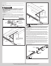
(2) 3/8”-16 x
3/4” Truss head
bolts and nuts
Bolt must extend into
the track to serve as
a roller stop
End bearing plate
Horizontal
track
Angle brace
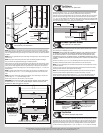
Horizontal
track
Sound framing members
Perforated angle- Bolted using
(2) 5/16” x 1-5/8” hex head lag
screws to ceiling member and
parallel to door
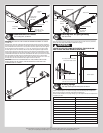
End bearing plate
Angle brace
Sound framing
members
Perforated angle- Bolted using
(2) 5/16” x 1-5/8” hex head lag
screws to ceiling member and
parallel to door.
End bearing plate
Horizontal
track
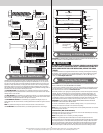
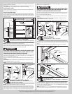
Spring Assembly
Tools: Ratchet Wrench, 3/8” Socket, 3/8” Wrench
16
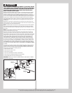
IMPORTANT: RIGHT HAND AND LEFT HAND IS ALWAYS DETERMINED FROM INSIDE THE
GARAGE LOOKING OUT.
NOTE: Identify the springs provided as either right hand wound (red winding cone), which
goes on the RIGHT HAND SIDE or left hand wound (black winding cone), which goes on the
LEFT HAND SIDE.
Facing the inside of the door, lay the torsion shaft on the floor at the rear of the horizontal
track. Lay the spring with the black color coded winding cone and the black color coded
cable drum, at the left hand end of the shaft. Lay the spring with the red color coded winding
cone and the red color coded cable drum, at the right hand end of the shaft. 1. Place the
center bearing bracket on the torsion tube. Then place each springs on their correct side of
the torsion tube. 2. The springs with the black winding cone on the left. 3. The springs with
the red winding cone on the right, as shown.
NOTE: The set screws used on all torsion counterbalance winding cones and cable drums,
are now colored red. DO NOT identify right and left hand by the set screw color.
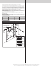
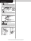
Lift the torsion shaft off the floor. Slide one end of the shaft through the end bearing bracket.
Extend the shaft through the bearing until the opposite end of the shaft can be inserted into
the other end bearing bracket. Equalize the amount that the shaft protrudes on each side.
Slide the center bearing bracket to the center of the torsion shaft. Secure the bracket to the
ceiling using perforated angle or wood blocking. Place the stationary cone(s) of the torsion
springs in line with the slots in the end bearing brackets and secure using (2) 3/8”-16 x
1-1/2” hex head bolts and nuts. Place the black drum over the left end of the torsion shaft
and the red drum over the right end.
Repeat for opposite side.
2. Black
winding cone
Black cable
drum
1. Center
bearing
bracket
3. Red
winding cone
Red cable drum
Torsion
shaft
10