


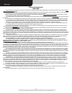

Please Do Not Return This Product To The Store. Contact your local Wayne-Dalton dealer. To find your local Wayne-Dalton dealer,
refer to your local yellow pages business listings or go to the Find a Dealer section online at www.Wayne-Dalton.com
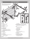
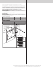
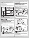
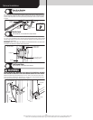
To attach the bottom jamb bracket, locate lower hole of the hole/ slot pattern of the 1st hole
set on the vertical track. Align the slot in the jamb bracket with the lower hole of the hole/ slot
pattern. Secure jamb bracket using (1) 1/4”-20 x 9/16” track bolt and (1) 1/4”-20 flange hex
nut. Repeat for other side.
Place the center jamb bracket over the lower hole of the hole/ slot pattern that is centered
between the bottom jamb bracket and flag angle of the 2nd hole set. Secure jamb bracket
using (1) 1/4”-20 x 9/16” track bolt and (1) 1/4”-20 flange hex nut. Repeat for other side.
If a top jamb bracket was included, secure it to vertical track using the lower hole of the hole/
slot pattern in the 3rd hole set and (1) 1/4”-20 x 9/16” track bolt and (1) 1/4”-20 flange hex
nut. Repeat for other side.
F.A. jamb
bracket
1/4”- 20 x
9/16”
Track bolt
1/4”- 20
Flange hex nut
Jamb bracket
in place
1st hole set
Lower hole of
hole/ slot pattern
Vertical track
2nd hole set 3rd hole set
Top of track
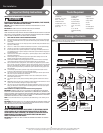
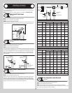
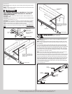
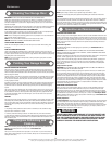
Bottom Corner Brackets
Tools: Power drill, 7/16” Socket driver
5
NOTE: The bottom section can be identified by the smallest graduated edge hinge of the
factory installed graduated edge hinges, see Parts Breakdown on page 2
Locate the left hand bottom corner bracket. Align the bottom corner bracket horizontally with
the top edge of the factory attached bottom corner bracket. Also align the bottom corner
bracket vertically with the left edge of the bottom section. Attach the bottom corner bracket
using (4) 1/4”- 20 x 11/16” self drilling screws and (1) 1/4” - 20 x 5/8” tamper proof screw,
as shown.
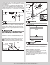
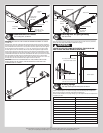
WARNING WARNING
FAILURE TO ENSURE TIGHT FIT OF CABLE LOOP OVER MILFORD PIN COULD
RESULT IN COUNTERBALANCE LIFT CABLE COMING OFF THE PIN, AL-
LOWING THE DOOR TO FALL, POSSIBLY RESULTING IN SEVERE OR FATAL
INJURY.
Uncoil the counterbalance cables. Place clevis pin into the inside tab of the bottom corner
bracket and slide the cable loop of the counterbalance lift cable onto pin. Continue sliding
clevis pin thru the outside tab of the bracket. Place a washer onto mildford pin and secure in
place using a cotter pin, as shown.
Insert a short stem track roller into the factory attached bottom corner brackets and another
into the #1 graduated end hinges at the top of the bottom section. Repeat for other side.
NOTE: Larger doors will use long stem track rollers with double graduated end hinges.
NOTE: Verify bottom weather seal is aligned with bottom section. If there is more than 1/2”
excess weather seal on either side, trim weather seal even with bottom section.
(4) 1/4”-20 x 11/16”
Self drilling screws
(1)1/4” - 20 x 5/8”
Tamper resistant
self drilling screw
Left hand bottom
corner bracket
End cap
Factory attached
bottom corner
bracket
Bottom weather
seal
Bottom
section
Counterbalance
lift cable
Bottom section
Short stem
track roller
Clevis pin
Left hand
bottom corner
bracket
End cap
Factory attached
bottom corner
bracket
Bottom
corner
bracket
Clevis
pin
Counterbalance
lift cable
Cotter pin
3/8”
Washer
Cotter pin
3/8” Washer
Bottom weather
seal
Cable
loop
Short stem
track roller
Double graduated
end hinge (Hinge
tube)
Long stem
track roller
Single graduated
end hinge (Hinge
tube)
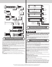
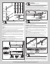
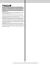
Bottom Section
Tools: Level, Wooden shims (if necessary)
6
Center the bottom section in the door opening. Level the section using wooden shims (if
necessary) under the bottom section.
Weather seal
Level
Bottom section
Wooden shims
(If necessary)
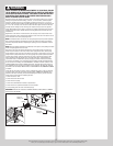
Vertical Tracks
Tools: Power Drill, 3/16” Drill bit, 7/16” Socket driver, Tape measure,
Level, Step ladder
7
IMPORTANT: IF YOUR DOOR IS TO BE INSTALLED PRIOR TO A FINISHING CONSTRUCTION
OF THE BUILDING’S FLOOR, THE VERTICAL TRACKS AND THE DOOR BOTTOM SECTION
ASSEMBLY SHOULD BE INSTALLED SUCH THAT WHEN THE FLOOR IS CONSTRUCTED, NO
DOOR OR TRACK PARTS ARE TRAPPED IN THE FLOOR CONSTRUCTION.
IMPORTANT: THE TOPS OF THE VERTICAL TRACKS MUST BE LEVEL FROM SIDE TO SIDE.
IF THE BOTTOM SECTION WAS SHIMMED TO LEVEL IT, THE VERTICAL TRACK ON THE
SHIMMED SIDE MUST BE RAISED THE HEIGHT OF THE SHIM.
Position the left hand vertical track assembly over the track rollers of the bottom section.
Make sure the counterbalance lift cable is located between the track rollers and the door
jamb. Drill 3/16” pilot holes into the door jamb for the lag screws.
Loosely fasten jamb brackets and flag angle to the jamb using 5/16” x 1-5/8” lag screws.
Tighten lag screws, securing the bottom jamb bracket to jamb, maintain 3/8” to 5/8” spac-
ing, between the bottom section and vertical track. Hang counterbalance lift cable over flag
angle. Repeat same process for other side.
7