


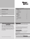
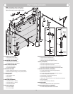
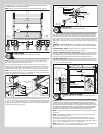

NOTE: The bottom jamb bracket is always the shortest bracket, while the center jamb
bracket is the next tallest. If three jamb brackets per side are included with your door, you will
have received a top jamb bracket, which is the tallest.
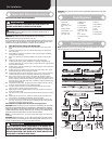
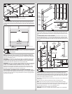
To attach the bottom jamb bracket, locate lower hole of the hole/ slot pattern of the 1st hole
set on the vertical track. Align the slot in the jamb bracket with the lower hole of the hole/ slot
pattern. Secure jamb bracket using (1) 1/4” - 20 x 9/16” track bolt and (1) 1/4” - 20 flange
hex nut. Repeat for other side.
Place the center jamb bracket over the lower hole of the hole/ slot pattern that is centered
between the bottom jamb bracket and flag angle of the 2nd hole set. Secure jamb bracket
using (1) 1/4” - 20 x 9/16” track bolt and (1) 1/4” - 20 flange hex nut. Repeat for other side.
If a top jamb bracket was included, secure it to vertical track using the lower hole of the hole/
slot pattern in the 3rd hole set and (1) 1/4” - 20 x 9/16” track bolt and (1) 1/4” - 20 flange
hex nut. Repeat for other side.
F.A. jamb
bracket
1/4”- 20 x
9/16”
Track bolt
1/4”- 20
Flange hex nut
Jamb bracket
in place
1st hole set
Lower hole of
hole/ slot pattern
Vertical track
2nd hole set 3rd hole set
Top of track
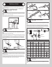
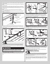
Bottom Corner Brackets
Tools Required: Power Drill, 7/16” Socket driver, Tape measure, Saw horses
6
NOTE: Refer to Package Contents / Parts Breakdown, to determine which bottom corner
brackets you have.
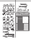
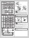
Uncoil the counterbalance lift cables. Depending on which bottom corner brackets you have
(reference illustrations below), slip the loop at the ends of the counterbalance lift cable over
the milford pin of the bottom corner bracket or secure the cable loop to the clevis pin and
bottom corner bracket using a flat washer and a cotter pin. Repeat for other bottom corner
bracket.
WARNINGWARNING
FAILURE TO ENSURE TIGHT FIT OF CABLE LOOP OVER MILFORD PIN
COULD RESULT IN COUNTERBALANCE LIFT CABLE COMING OFF THE PIN,
ALLOWING THE DOOR TO FALL, POSSIBLY RESULTING IN SEVERE OR
FATAL INJURY.
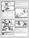
Starting on the left hand side, attach the left hand bottom corner bracket to the left corner
of the bottom section, making sure it is seated to the edges of the end cap, using 1/4” - 20
x 11/16” self drilling screws, roller spacer (if applicable) washer (if applicable) and (1) 1/4” -
14 x 5/8” tamper resistant self drilling screw. Repeat for right hand bottom corner bracket.
NOTE: All doors are provided with the tamper resistant fastener for the bottom corner
brackets. However, the professional installer is most likely to have the proper tool to install
this fastener. If the homeowner does not have the proper tool to install the tamper resistant
fastener, use a regular 1/4” - 20 x 11/16” self drilling screw in its place.
NOTE: Check to ensure cable loop fits tightly over the milford pins.
Insert a short stem track roller with roller spacer into the bottom corner bracket. Repeat for
other side.
NOTE: Verify bottom weather seal (bottom seal) is aligned with door section. If there is more
than 1/2” excess bottom weather seal on either side, trim bottom weather seal even with
door section.
Roller spacer
Counterbalance
cable loop
(2) 1/4”-20 x 11/16”
Self drilling screws
1/4”-14 x 5/8”
Tamper resistant
self drilling screw
Short stem track roller
Milford pin
Bottom corner
bracket
End cap
Counterbalance
lift cable
Bottom weather
seal
Bottom
section
End cap
Counterbalance
lift cable
Bottom weather
seal
Bottom
section
Roller spacer
Short stem track roller
Bottom corner
bracket
(4) 1/4”-20 x 11/16”
Self drilling screws
1/4”-14 x 5/8”
Tamper resistant
self drilling screw
Counterbalance
cable loop
Cotter pin (attached into
place from opposite
side of bottom bracket)
Clevis pin (inserted through
cotter pin and bent into place)
Washer
End cap
Roller spacer
Counterbalance
cable loop
(4) 1/4”-20 x 11/16”
Self drilling screws
Bottom section
Short stem track roller
Milford pin
Bottom corner
bracket
Counterbalance
lift cable
Bottom weather
seal
1/4”-14 x 5/8”
Tamper resistant
self drilling screw
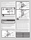
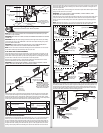
Graduated Hinge / Strut Attachment
Tools Required: Power drill, 7/16” Socket driver, Saw horses, Tape Measure
7
NOTE: Refer to door section identification, located in the pre-installation section of this
manual to determine what size sections you need to use as your lock (second) section, inter-
mediate (third) section, intermediate (fourth) section, intermediate (fifth) section, intermediate
(sixth) section, intermediate (seventh) section, intermediate (eighth) section and top section.
Measure your sections to make sure they are the correct height as indicated on the chart.
NOTE: The graduated end hinges can be identified by the number stamped on the lower
hinge leaf. The #1 graduated end hinges serves as end hinges on the bottom section. The #1
graduated end hinges also serves as center hinges on all sections, except for the top section.
NOTE: The #2 graduated end hinges serves as end hinges on the Lock section.
NOTE: The #3 graduated end hinges serves as end hinges on the Intermediate I section.
NOTE: The #4 graduated end hinges serves as end hinges on the Intermediate II section.
NOTE: The #5 graduated end hinges serves as end hinges on the Intermediate III section.
NOTE: The #6 graduated end hinges serves as end hinges on the Intermediate IV section.
NOTE: The #7 graduated end hinges serves as end hinges on the Intermediate V section.
NOTE: The #8 graduated end hinges serves as end hinges on the Intermediate VI section.
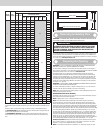
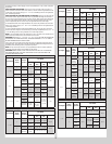
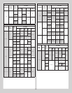
NOTE: Refer to the strutting schedules below to determine the placement of strut(s) on your
door. Be sure to use the proper schedules for the type of door model and the size of your
door.
IMPORTANT: WHEN REFERRING TO THE STRUTTING SCHEDULES, DETERMINE HOW
MANY STRUTS YOUR DOOR NEEDS AND ON WHAT SECTIONS THEY ARE NEEDED TO BE
INSTALLED. ALSO BE SURE TO USE THE CORRECT STRUTTING SCHEDULE FOR ALUMINUM
DOORS OR STEEL DOORS DEPENDING ON THE MATERIAL YOUR DOOR IS MADE OF. ALSO
USE THE CORRECT STRUTTING SCHEDULE FOR THE PROPER COLOR OF YOUR DOOR.
NOTE: Sections not noted in the strutting schedule, do not require a strut. All strut(s) are
placed at the top of the section(s).
Strutting Schedule Key:
TS = Top Section I1 = Intermediate Section #1
IW = Intermediate Section With Windows LS = Lock Section
I6 = Intermediate Section #6 BS = Bottom Section
I5 = Intermediate Section #5 ES = Every Section gets a strut.
I4 = Intermediate Section #4 RS = Remaining Sections gets a strut.
I3 = Intermediate Section #3 2S = 2” Strut
I2 = Intermediate Section #2 3S = 3” Strut
Using sawhorses, lay sections together on a flat smooth surface. Ensure the appropriate
8