


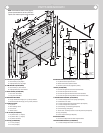
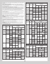
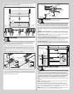
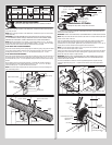

SECURING WITH 1/4” - 20 X 5/8” SELF-TAPPING SCREWS. THERE SHOULD BE NO GAP
BETWEEN THE HINGE LEAFS AND THE SECTIONS.
NOTE: Install lock at this time (sold separately). See optional installation step, Side Lock.
Intermediate hinge(s)
Left
end hinge
Right
end hinge
1/4”-20 x 11/16” Self drilling screw locations
Double end
hinges
Upper
hinge
leafs
Lock section
Vertical
tracks
Double end
hinges
Single end
hinges
Single end
hinges
Bottom
section
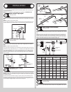
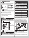
Top Fixtures
Tools Required: Power drill, 7/16” Socket driver, Saw horses
13
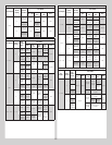
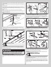
NOTE: Depending on your door, you may have Top Fixture Bases and Top Fixture Slides
or you may have Top Fixture Assemblies. Refer to Illustrations / Package Contents / Parts
Breakdown, to determine which Top Fixtures you have.
Starting on the left hand side, align the top fixture base 3” down from the top section or
below strut and even with the edge of the top section. The slotted half of the top fixture base
should be facing upwards. Fasten to section through end cap using (4) 1/4” - 20 x 11/16”
self drilling screws. Insert short stem track roller into top fixture slide. Repeat for other side.
NOTE: If needed, ensure the top fixture slides are able to slide back and forth along the top
fixture bases. If needed, loosen the (2) 1/4” - 20 flange hex nuts. The top fixture slide will be
tightened and adjusted later, in step, Adjusting Top Fixtures.
(4) 1/4”-20 x 11/16”
Self drilling screws
Top fixture
base
(2) 1/4”-20 Flange
hex nuts
Top fixture
slide
Short stem
track roller
End
cap
Top section
Top
section
End
cap
3”
(4) 1/4”-20 x 11/16”
Self drilling screws
Strut
Top section
Starting on the left hand side, align the top fixture base on top of the corner of the top section
and even with the edge of the section. Fasten to section through end cap using (4) 1/4” - 20
x 11/16” self drilling screws. Loosely secure the top fixture slide to the top fixture base using
(1) 5/16” - 18 x 3/4” carriage bolt and (1) 5/16” - 18 hex nut. The top fixture assembly will
be tightened and adjusted later, in step, Adjusting Top Fixtures. Insert short stem track roller
into top fixture slide. Repeat for other side.
5/16”-18 x 3/4”
Carriage bolt
(4) 1/4”-20 x 11/16”
Self drilling screws
Top fixture
base
Top fixture
slide
5/16”-18
Hex nut
End
cap
Top section
Short stem
track roller
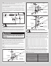
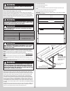
Top Section
Tools Required: Hammer, Step ladder, Tape measure
14
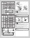
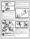
Place the top section in the opening. Temporarily secure the top section by driving a nail in
the header near the center of the door and bending it over the top section. Now, flip up the
hinge leaves, hold tight against section, and fasten center hinges first and end hinges last
(refer to step, Stacking Sections). Vertical track alignment is critical. Position flag angle or wall
angle between 1-11/16” (43 mm) to 1-3/4” (44 mm) from the edge of the door; tighten the
bottom lag screw. Flag angles or wall angles must be parallel to the door sections. Repeat for
other side.
IMPORTANT: THE DIMENSION BETWEEN THE FLAG ANGLES OR WALL ANGLES MUST BE
DOOR WIDTH PLUS 3-3/8” (86MM) TO 3-1/2” (89 MM) FOR SMOOTH, SAFE DOOR OPERA-
TION.
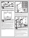
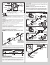
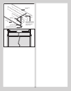
FOR QUICK INSTALL TRACK: Complete the vertical track installation by securing the jamb
bracket(s) and tightening the other lag screws. Repeat for other side.
FOR FULLY ADJUSTABLE TRACK OR RIVETED TRACK: Complete the vertical track instal-
lation by securing the jamb bracket(s) and tightening the other lag screws. Push the vertical
track against the track rollers so that the track rollers are touching the deepest part of the
curved side of the track; tighten all the track bolts and nuts. Repeat for other side.
FOR ANGLE MOUNT TRACK: Complete the vertical track installation by securing the jamb
bracket(s) and or tightening the other lag screws. Push the vertical track against the track
rollers so that the track rollers are touching the deepest part of the curved side of the vertical
track, as shown. Repeat for other side.
Top section
Top
section
Nail
Door width
+ 3-3/8” to 3-1/2”
1-11/16”
to 1-3/4”
Flag
angle
Vertical track
against track rollers
Flag angle or
wallangle assembly
Top of flag angle or
Top of wallangle assembly
Drawbar Operator Bracket
Tools Required: Power drill, 7/16” Socket driver, Level, Tape measure, Step
ladder
15
IMPORTANT: WHEN CONNECTING A TROLLEY TYPE GARAGE DOOR OPENER TO THIS DOOR,
A WAYNE-DALTON OPERATOR/ TROLLEY BRACKET MUST BE SECURELY ATTACHED TO
THE TOP SECTION OF THE DOOR IF ONE HAS BEEN PROVIDED, ALONG WITH ANY STRUTS
PROVIDED WITH THE DOOR (IF A WAYNE-DALTON OPERATOR/ TROLLEY BRACKET WAS NOT
PROVIDED WITH YOUR DOOR, THAN USE THE ONE PROVIDED BY YOUR OPERATOR MANU-
FACTURER). THE INSTALLATION OF THE OPERATOR MUST BE ACCORDING TO MANUFAC-
TURER’S INSTRUCTIONS AND FORCE SETTINGS MUST BE ADJUSTED PROPERLY.
NOTE: For retro fit applications, the drawbar operator bracket must be aligned with an exist-
ing operator.
NOTE: Refer to illustrations to determine which top fixtures were supplied with your door.
Follow the corresponding step below:
Place the bottom half inside the top half and flush against the inside surface of the top
section. Adjust both the top and bottom halves out as far apart as possible on the section
surface. Secure the drawbar operator bracket bottom half and the top half together using (4)
5/16” - 18 x 1/2” carriage bolts and (4) 5/16” - 18 flange hex nuts.
NOTE: Install the 5/16” - 18 x 1/2” carriage bolts and the 5/16” - 18 flange hex nuts as far
apart as possible, prior to securing both top and bottom halves together.
13