


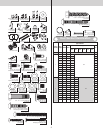
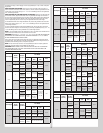
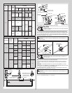

Strutting Schedule For Model 8500 Aluminum (White, Almond & Taupe Colored Doors)
Door
Heights
Section
Quantity
Door
Configu-
rations
Door Widths
6’0” -
9’0”
10’0”
12’0” -
14’0”
15’0” -
16’0”
17’0” -
18’0”
20’0”
> 8’0”
5
Solid 2S, TS
2S, TS /
2S, I1
2S, TS / 2S, I2 / 2S,
I1 / 2S, BS
N/A
Top (Win-
dows)
2S, TS
2S, TS /
2S, I1
2S, TS /
2S, I2 /
2S, I1 /
2S, BS
3S, TS /
2S, I2 /
2S, I1 /
2S, BS
Inter-
mediate
(Windows)
2S, TS
2S, TS /
2S, IW
2S, TS / 2S, IW / 2S,
I1 / 2S, BS
6
Solid 2S, TS
2S, TS /
2S, I2
2S, TS /
2S, I2 /
2S, I1 /
2S, BS
2S, TS /
2S, I3 /
2S, I2 /
2S, I1 /
2S, BS
N/A
Top (Win-
dows)
2S, TS
2S, TS /
2S, I2
3S, TS /
2S, I3 /
2S, I2 /
2S, I1 /
2S, BS
Inter-
mediate
(Windows)
2S, TS
2S, TS /
2S, IW
2S, TS /
2S, IW /
2S, I1 /
2S, BS
2S, TS /
2S, IW /
2S, I2 /
2S, I1 /
2S, BS
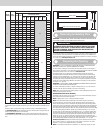
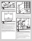
Strutting Schedule For Model 8500 Aluminum (Brown Colored Doors)
Door Heights
Section
Quantity
Door Con-
figurations
Door Widths
6’0” - 10’0”
12’0” -
16’0”
17’0” -
18’0”
20’0”
< = 8’0”
4
Solid / Top
(Windows)
2S, TS
2S, TS / 2S,
LS / 2S, BS
3S, TS / 3S,
LS / 3S, BS
3S, ES
Intermediate
(Windows)
2S, TS / 2S,
IW / 2S, BS
3S, TS / 3S,
IW / 3S, BS
5
Solid / Top
(Windows)
2S, TS
2S, TS / 2S,
I1 / 2S, BS
3S, TS / 3S,
I1 / 3S, BS
3S, ES
Intermediate
(Windows)
2S, TS / 2S,
IW / 2S, BS
3S, TS / 3S,
IW / 3S, BS
> 8’0”
5
Solid / Top
(Windows)
2S, TS
2S, TS / 2S,
I2 / 2S, I1 /
2S, BS
3S, TS / 3S,
I2 / 3S, I1 /
3S, BS
N/A
Intermediate
(Windows)
2S, TS / 2S,
IW / 2S, I1 /
2S, BS
3S, TS / 3S,
IW / 3S, I1 /
3S, BS
6
Solid / Top
(Windows)
2S, TS
2S, TS / 2S,
I2 / 2S, I1 /
2S, BS
3S, TS / 3S,
I3 / 3S, I2
/ 3S, I1 /
3S, BS
N/A
Intermediate
(Windows)
2S, TS / 2S,
IW / 2S, I1 /
2S, BS
3S, TS / 3S,
IW / 3S, I2
/ 3S, I1 /
3S, BS
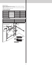
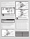
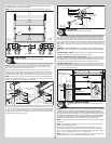
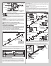
#1Center hinge(s)
#1 Graduated
end hinge
Short stem
track roller
Lower
hinge leaf
#2 Graduated end hinge
(short stem track roller
inserted into tube
furthest from section)
1/4”-20 x 7/8” Self drilling
screw locations
#1 Center hinge(s)
End stile
End stile
(2) Strut clips
(2) 1/4”-20 x 7/8”
Self drilling screws
(2) 1/4”-20 x 7/8”
Self drilling screws
Graduated
end hinge
Center hinge
Strut installation across Graduated end hinge and center hinges
Strut installation at top of section
Strut
(2) Strut clips
Strut
(2) 1/4”-20 x 7/8”
Self drilling screws
Strut
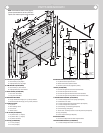
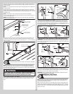
Step Plate
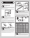
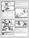
Tools Required: Tape measure, Power drill, Drill bits, 7/16” Wrench, Phillips head
screwdriver, Saw horses
8
Locate the center most center stile on the bottom section of the door. On the inside of the
door and using the pre-punched holes at the bottom of the center stile as a template, drill (2)
7/32” dia. holes through the section. Using the previously drilled holes as a guide, enlarge
the holes from outside the door to 7/16” dia. and assemble the outside and inside step plates
to the section using (2) #8 x 1-5/8” screws.
CAUTION: DO NOT DRILL THROUGH OR ENLARGE HOLES ON THE INSIDE OF THE
DOOR SECTION.
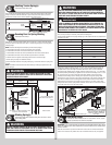
Outside step plate
Bottom section outside
Holes enlarged
to 7/16” diameter
Inside step plate
Bottom section inside
Pre-punched
holes
(2) #8 x 1-5/8” screws
8” Max.
mounting
height
Lift Handle
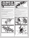
Tools Required: Tape measure, Pencil, Power drill, 9/32”/1/2” Drill bits, 1/4”
Wrench, Saw horses
9
NOTE: Doors with a Keyed lock do not require this lift handle.
Locate the inside center stile or the desired lift handle location on the lock (2nd) section
of the door. Position the lower hole in the lift handle 4” from the bottom of the lock (2nd)
section.
IMPORTANT: THE DISTANCE BETWEEN THE STEP PLATE AND THE MIDDLE OF THE LIFT
HANDLE MUST BE 20” MINIMUM TO 30” MAXIMUM. IF NECESSARY REPOSITION THE UPPER
LIFT HANDLE TO STAY WITHIN THE REQUIRED DIMENSION.
Using the lift handle holes as a template, drill (2) 9/32” dia. holes through the lock section.
Enlarge the holes from the outside the door to 1/2” dia.
CAUTION: DO NOT DRILL THROUGH OR ENLARGE HOLES ON THE INSIDE OF THE
DOOR SECTION.
Assemble the outside and inside lift handles to the lock section using (2) spacers, (2) 1/4” -
20 x 2-1/2” carriage bolts and (2) 1/4” - 20 hex nuts.
11