


Please Do Not Return This Product To The Store. Call Us Directly! Our Trained Technicians Will Answer Your Questions and/or Ship Any Parts You May Need
You can reach us Toll Free at 1-888-827-3667 for Consumer Assistance or online at www.wayne-dalton.com
20
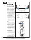
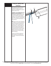
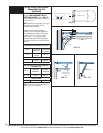
Power Connection
(Permanent Wiring Option)
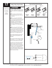
Tools Needed:
Needle Nose Pliers
Pliers/Wire Cutters
Flat Tip
Screwdriver
TO AVOID ELECTRICAL SHOCK,
DISCONNECT POWER AT THE FUSE/
BREAKER BOX BEFORE PROCEEDING.
IMPORTANT: CHECK YOUR LOCAL
ELECTRICAL CODES. IF YOUR LOCAL CODE
REQUIRES PERMANENT WIRING, USE THE
SPECIFICATIONS CALLED FOR AND
INSTRUCTIONS ILLUSTRATED.
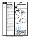
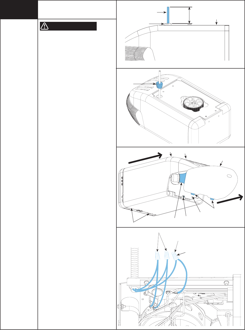
Permanent Wiring Procedure
1. Ensure power cord is disconnected from
electrical power.
2. Cut power cord 1/2” – 1” from strain
relief/bushing.
3. Use needle nose pliers to remove strain
relief bushing from frame. Squeeze tabs in
on underside of bushing and work bushing
out of hole.
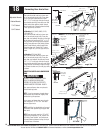
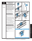
4. Pull or strip off remaining section of outer
insulation from power cord.
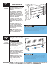
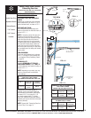
5. Remove lens by pressing up on both sides
of the bottom of the lens at the junction of
the housing, releasing the locking tabs,
and pulling forward; remove light bulb (if
installed).
6. Remove the housing from the chassis by
removing the screw securing the
housing to the chassis. Press on the
locking tabs and slide the cover off the
chassis.
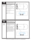
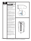
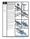
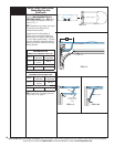
7. Pull the three wires into the opener;
strip 1/2” of insulation from the black,
white, and green wires.
8. Using wire nuts for 14-18 AWG wire,
connect the black wire to black wire, the
white wire to white wire and the green
wire to green wire. Make sure connections
are secure.
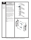
9. Replace opener cover.
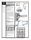
Reconnect the power at the fuse/ breaker
box, as soon as power is applied to the unit,
the light on the opener will blink once to
indicate a successful self check of the
controls.
WARNING
Live & Neutral
Ground
I
Opener
1/2” To 1”
Power Cord
Strain Relief Bushing
Strain Relief
Bushing
Screw
Lens
Light Bulb
Tabs
Tab
Chassis
Tabs
Housing
Wire Nuts