


Please Do Not Return This Product To The Store. Call Us Directly! Our Trained Technicians Will Answer Your Questions and/or Ship Any Parts You May Need
You can reach us Toll Free at 1-888-827-3667 for Consumer Assistance or online at www.wayne-dalton.com
9
11
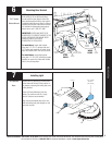
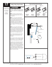
Wired Infrared Safety Sensor
Installation
Tools Needed:
Ratchet Wrench
Tape Measure
Power Drill
3/16” Drill Bit
7/16” Socket
Driver
7/16” Wrench
Pencil
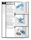
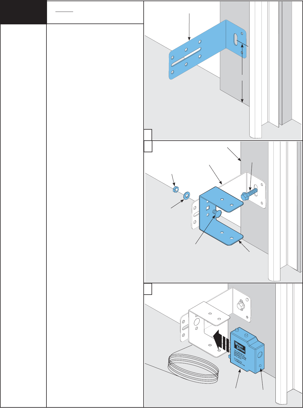
IMPORTANT: BOTH WALL BRACKETS
MUST BE MOUNTED AT THE SAME HEIGHT
FOR PROPER ALIGNMENT.
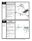
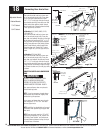
Note: Use Steps a-c for installing sensors
on both sides of the garage door.
a. Select and mark with a pencil, a
mounting location no more than
5 inches above the floor to center line of
wall mounting bracket. The safety sensors
should be mounted as close to the door
track or inside edge of the door as
possible to offer maximum entrapment
protection. It is very important that both
wall mounting brackets be mounted at
the same height for proper alignment.
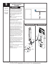
b. Drill pilot holes, using a 3/16” drill bit.
Using two 5/16” x 1-1/2” lag screws,
permanently mount the wall mounting
brackets to both door jambs. In some
installations it may be necessary to attach
a wooden spacer to the wall to achieve
the required alignment.
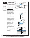
Attach the “U” brackets to the wall
mounting brackets with 1/4”-20 x 1/2”
carriage bolts, washers and nuts.
Insert the bolts from the inside of the
“U” bracket and hand-tighten.
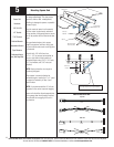
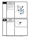
IMPORTANT: IDENTIFY WHICH SIDE OF THE
GARAGE DOOR IS EXPOSED TO THE MOST
SUNLIGHT. MOUNT THE SENDING UNIT (UNIT
WITHOUT LED) ON THE SIDE WHICH IS
EXPOSED TO THE MOST SUN. SUNLIGHT
MAY AFFECT THE SAFETY SENSORS, AND
THIS ORIENTATION WILL HELP REDUCE THE
EFFECT.
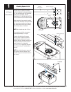
c. Attach the sending and receiving safety
sensors to the “U” brackets by inserting
all three tabs into the respective holes.
Wall Mounting Bracket
5”
Washer
Nut
1/4”-20 x 1/2”
Carriage Bolt
5/16” x 1-1/2”
Lag Screw
Door Jam
U-Bracket
Wall Mounting
Bracket
Receiving
Unit
LED
a
c
b