


5
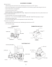
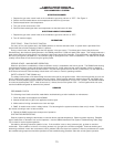
COMBUSTION CHAMBERS
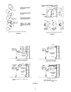
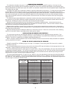
The combustion chamber sizes given in Figure 5 are based on the maximum rated BTU capacity. If the input is to be
permanently set at a reduced rate, the combustion chamber floor area can be reduced proportionately to the proposed input,
allowing 200,000 BTU (211000kJ) per square foot (.093m
2
) of combustion chamber floor area and proportioning the length about
70% greater than the width.
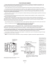
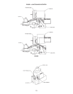
The height of the walls of the combustion chamber is generally determined by the grate line. The side and front walls should
be built about 2” (50.8mm) above the grate line, covering the grate lugs and covering the bases of the water legs of boilers
about 3” (76.2mm) or 4” (101.6mm) to avoid heating sections that may be filled with sediment. The back wall should be carried
one or two courses higher and overhung to deflect hot gases from direct impingement on the rear heat exchanger surfaces.
Hard firebrick should be used for the overhung section to prevent erosion of the brick at this point by the high velocity gases
m9moving over it.
The remaining open spaces between the combustion chamber and ash pit walls should be filled with loose insulation. Since
this insulation may not stand combustion chamber temperatures, the top course of the combustion chamber walls be laid flat,
extending to, and fitting the contour of the firebox and covering the loose insulation.
Always use cement furnished by the brick manufacturer for cementing insulating firebrick. It should be thinned to the
consistency of a very thick cream so that the brick can be dipped into it and set in place. The use of other cement or mortar
may impair the insulating and radiating qualities of the brick.
Magnesia block insulation, common brick, hard fire brick, dry sand and/or expanded mica products such a “Vermiculite” or
“Zonolite” can be used to back up the insulating firebrick. High temperature furnace cement can be used to seal the openings
around the burner and furnace.
Approved insulating bricks are: Babcock & Wilcox No. K-23 and No. K-26, A. P. Grenn No. G-23 and No. G-26, Armstrong
Cork No. A-23 and No. A-26 an Johns Manville No. JM-23 and No. JM-26.
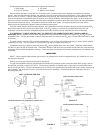
INSTALLATION OF BURNER AND CONTROLS
The inshot power gas burner was designed especially for converting gun fired oil designed furnaces and boilers. Due
consideration was given to making it as simple and easy to install and service as possible without weakening its durability or
efficiency. The burner is supplied as a completely assembled package unit.
NOTE: The burner must be installed in such a manner that they unit and all controls will be readily accessible for inspection,
cleaning, adjustment and repairs.
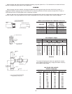
SIZING OF INPUT IN RELATION TO FURNACE
FIGURE 140,000 BTUs (147700KJ) per gal. of oil input. For example: Furnace rating 0.60 G.P.H. then 0.60 x 140,000 =
72,000 BTUs input rate
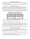
The orifice spud supplied with all burners is the size for the minimum BTU input of the burner for the type gas shown on the
rating plate. Figure 6 shows the correct drill size for various inputs.
The correct manifold pressure for natural gas is 3.5” w.c(871.8 Pa). Only minor adjustments in the input rate should be made
by adjusting the pressure regulator. The minimum manifold pressure should be 3.0” w.c. (747.2Pa) and the maximum pressure
should be 3.5 w.c. (871.8 Pa) the next size larger or smaller orifice size should be used if the desired input rating cannot be
obtained within the above manifold pressure adjustment range.
The correct manifold pressure for L.P. gas is 10” w.c. (2491Pa), only minor adjustments in the input rate should be made by
adjusting the pressure regulator. The minimum manifold pressure should be 9.5” w.c. (2366 Pa), the maximum pressure 10.0”
w.c. (2491 Pa). If the desired input rating cannot be obtained within the above manifold pressure and adjustment range then the
next size larger or smaller drill should be used.
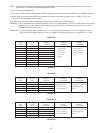
B.T.U. (kW) NATURAL GAS PROPANE GAS
INPUT 3 1/2” (871.8Pa) W.C.P. 10” (2491 Pa) W.C.P.
PER HOUR Drill Size Drill Size
50,000 (14.65) #30 (3.264mm) #45 (2.083mm)
75,000 (21.98) 5/32 (3.967mm) #41 (2.438mm)
90,000 (26.38) #17 (4.394mm) #37 (2.642mm)
100,000 (29.31) #14 (4.623mm) #35 (2.794mm)
125,000 (36.63) #5 (5.22mm) 1/8 (3.175mm)
130,000 (38.1) #4 (5.309mm) #30 (3.264mm)
150,000 (43.96) #1 (5.791mm) #29 (3.454mm)
160,000 (46.89) 15/64 (5.954mm) #28 (3.569mm)
175,000 (51.29) C (6.147mm) #26 (3.734mm)
180,000 (52.75) 1/4 (6.35mm) #25 (3.797mm)
200,000 (58.61) G (6.629mm) #22 (3.988mm)
225,000 (65.94) J (7.036mm) #19 (4.216mm)
242,000 (70.92) L (7.366mm) #17 (4.394mm)
250,000 (73.27) M (7.493mm) #16 (4.496mm)
FIGURE 6