


18
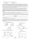
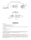
To measure flame current, first shut off the power to the system and then remove the flame sensing lead wire form the
electrode terminal and insert a 0-50 DC microamp meter in series with the sensor electrode and the sensor lead wire. “Plus”
terminal of meter to component board and “negative”: terminal to sense electrode. Energize the ignitor. If the meter reads
below zero, shut the system off and reverse meter leads.
Once the flame is established, assure that the flame current is above the minimum specified. If not, assure that the system
has the proper input voltage, and ten relocate the sensor electrode in the flame pattern until flame current is increased.
Once the flame has been established and the system is in its heat cycle, occasional sparking may occur. This is common in
some installations and is not significant. Sparking will not damage the ignitor.
7. Ambient
Temperatures
The 05-16 is designed to operate over the temperature range of -40 to 150 F (-40 to 65.56 C). Care should be taken to
insure that it operates within this range. If these limits are exceeded, the ignitor should be relocated to an area that is
within this temperature range.
8. Relative Humidity
The 05-16 is coated for moisture resistance to 90 percent relative humidity. Caution should be taken to protect the
component board against direct exposure to water.
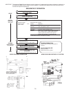
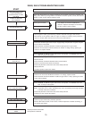
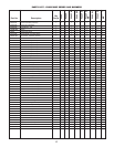
SERVICE HINT, DIAGNOSIS AND CORRECTIVE MEASURES
WHAT’S WRONG WHY WHAT TO DO
1. Lockout Occurs 3-10 1. Reverse polarity. Para. 1.
seconds after ignition. 2. System improperly grounded Para. 2.
3. Gas pressure too high, causing Check to ensure input pressure
flame to lift off burner. as specified on manufacturer’s
data plate.
4. Sensor probe incorrectly Para. 6.
positioned in flame pattern.
2. Flame not established. Spark gap too small. Para. 3a
Arching to ground. Spark too large. Para. 3a.
3. No spark. Corroded connector. Para. 3b.
4. Arching other than across gap. 1. Cracked or dirty insulator. Para. 3c.
2. Broken high voltage lead. Para. 3c.
Weak Spark. High voltage lead too close to Para. 3e.
metal surface.
No flame. Valve malfunction. Para. 4.
Low flame current and/or Electrode improperly placed. Para. 5.
nuisance lockouts.
Nuisance lockouts. 1. Flame current falls below 2.5 uA Para. 6.
2. Low gas pressure. Check to ensure that manifold
pressure meets manufacturer’s
specifications.
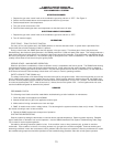
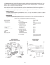
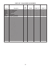
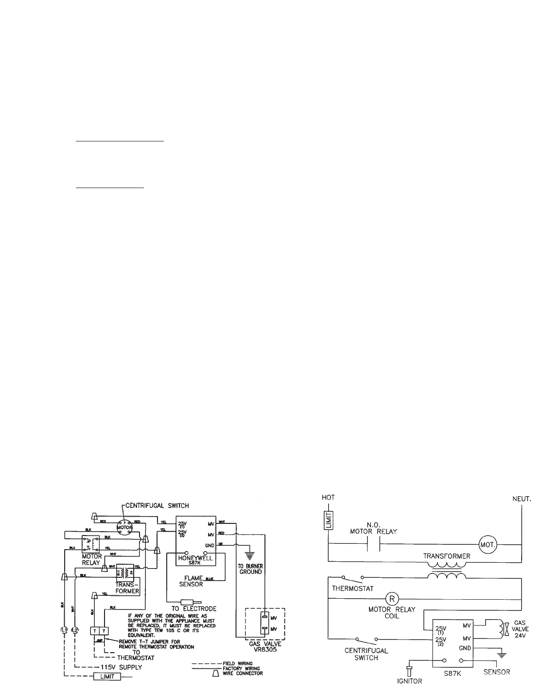
WIRING DIAGRAM
HONEYWELL S87KDI SYSTEM
WIRING DIAGRAM
LADDER FORM