


17
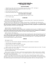
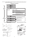
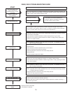
TROUBLESHOOTING
Although the following tests can be made using standard volt meter, it is quicker and more convenient to use a Fenwal
Model 05-125539-001 Test Adapters.
PRELIMINARY CHECKS
1. Input Polarity
If a spark is present and the gas valve opens for the flame establishing period but then locks out at the end of other
to ten seconds, check the input voltage at Terminals 1 and 6 for the proper polarity. Terminal 1 should be “hot”; 14AVC
(05-16) with respect to ground. Terminal 6 is neutral, or zero voltage, with respect to ground.
2. Improper Grounding
If a flame is present during the Trial for Ignition period but th system shuts down, insure that the burner is properly
grounded. If the burner is not grounded, the flame monitoring signal will not function and the system will go into lockout.
Check for loose or corroded terminals and replace if necessary. Insure good electric connection by scraping paint or any
other foreign matter off the area where ground connection is made.
It is equally important to be certain that the electrode bracket assembly is properly grounded. The bracket should be
common with the ground lead on the input connector (ground terminal 6). If the bracket is not properly grounded,
damage to the ignitor can result.
3. Inoperative High V
oltage
If there is no spark or sparking is intermittent, check the following after disconnecting voltage to the system.
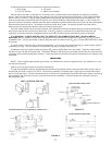
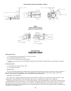
a. Check spark gap. Gap should be 1/8 (3.175mm)+/- 1/32”(.7937mm) form H.V. to ground.
CAUTION: NEVER REPLACE THE COMPONENT BOARD WITHOUT FIRST CHECKING TO INSURE THAT THE
ELECTRODE HAS THE PROPER GAP. IF THE GAP IS TOO WIDE, DAMAGE TO THE IGNITOR CAN RESULT.
b. Check electrode leads and determine there is no corrosion at the terminals. If there is corrosion, clean it off.
c. Check ceramic insulators for cracks, foreign matter, and carbon. If there are cracks, replace electrodes. If there is
carbon or foreign matter, clean it off.
d. Check high voltage lead wire for cracks or breaks. If there are cracks, breaks or chaffing, replace high voltage wire.
e. Check that the high voltage lead wire is not too close to a metal surface to insure that arcing will not occur at any
point other than across the H.V. electrode. Also, insure that the high voltage lead wire is not taped or connected to a
metal frame along its length, sharp metal edges, or crossing, do not bundle with other wires. Always leave one inch
spacing between the high voltage lead wire and any other metal or wires.
f. For best operation, the high voltage wire should be short as possible and should not exceed 23 inches (584.2 mm) in
length.
g. Check to insure that the high voltage terminal is clear of dust, moisture or any foreign matter that could create high
voltage leakage to ground.
4. V
alve Malfunction
With power applied to the ignitor, sparking should occur and the solenoid valve should open simultaneously. If sparking
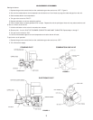
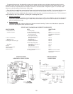
occurs but the valve does not open, place a volt meter between Terminal 4 on the input connector and ground (or across
valve). (terminals 4 (valve) and 6 (ground) in Figure 1). If voltage is present and the valve does not open, remove wires
from the valve terminals and retest the valve on a known voltage source. If valve still does not function, it should be
replaced. If the voltage is not present at Terminals 4 and 6, the ignitor should be replaced. Check p.c. connection area.
(clean with soft rubber eraser only). Also, check the terminals in the plastic connector for good contact.
The valve relay is rated for 24VAC on th 05-16, at .5 amps. If a valve is used with a higher current rating than that
specified, damage can result to the relay contacts.
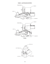
5. Electrode Placement
a. Electrode should be placed so optimum flame current is achieved for proper application.
b. Flame should not impinge on any portion of ceramic insulator.
6. Flame Current
The flame detector circuit uses the ionized gas flame to conduct the flame signal. This signal is a small DC current
which can be measured directly with a 0 to 50 microamp meter.
Although the minimum flame current necessary to keep the 05-16 ignitor from going into lockout is 2.5 ,microamps, the
lowest recommended is 5.0 microamps. These ignitors can stand flame currents as high as 30 to 40 microamps.