


11
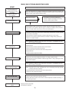
All adjustments below must be made with the following instructions:
1. Draft Gauge 3. CO Tester
2. O
2
or CO
2
Analyzer 4. Water Column Gauge
After the burner has been in operation for 10 minutes and if a neutral pressure point adjuster was installed, proceed as
follows. Start from the wide open position and gradually close the neutral pressure point adjustment. Crack observation door
about 1/8 inch (3.175mm). Then by holding match flame along opening, the neutral pressure point can be determined. The
flame should be drawn in below the center of the door and it should be blown outward above the center. In other words, the
pressure inside the combustion chamber should be above atmospheric pressure above the burner flame and below atmospheric
pressure below the burner flame. The pressure should be neutral at the center. Closing the adjuster lowers the neutral
pressure point and opening the adjuster raises the neutral pressure point.
Once the neutral pressure point has been adjusted, the combination air shutter should be adjusted so that the percent CO
2
test must be made at the inlet side of the draft hood. If the CO
2
reading is not within the recommended limits, then the
combustion air shutter should be re-adjusted and then the neutral pressure point be rechecked and reset if necessary.
IT IS ESSENTIAL TO MAKE CERTAIN THAT THE PRODUCTS OF COMBUSTION DO NOT CONTAIN CARBON
MONOXIDE, CO. It is possible to have flame impingement on cold surfaces with resultant CO even if CO
2
and O
2
are within
acceptable limits. The flue gas sample is taken through the same hole used for the CO
2
test. CO test instrument must be used
for this test.
The most common causes of CO are flame impingement on cool surface and insufficient primary air, both of which could be
caused by over firing. The only answer is to reduce the firing rate or increase the primary air.
Combustion efficiency is determined by the percent CO
2
and the temperature of the flue gases. These two measurements
are taken on the inlet side of the draft hood. Combustion efficiency and stack loss calculators provide slide rule convenience for
correlating CO
2
and stack temperature readings. These calculators are available from several manufactures of combustion test
equipment.
IMPORTANT
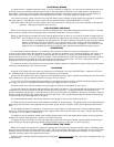
DRAFT - When installing Wayne power gas burners in oil fired boilers a minimum negative draft of .02” (4.982 Pa) w.c. over
fire must be maintained.
Refer to your local gas company and codes for assistance.
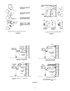
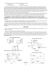
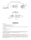
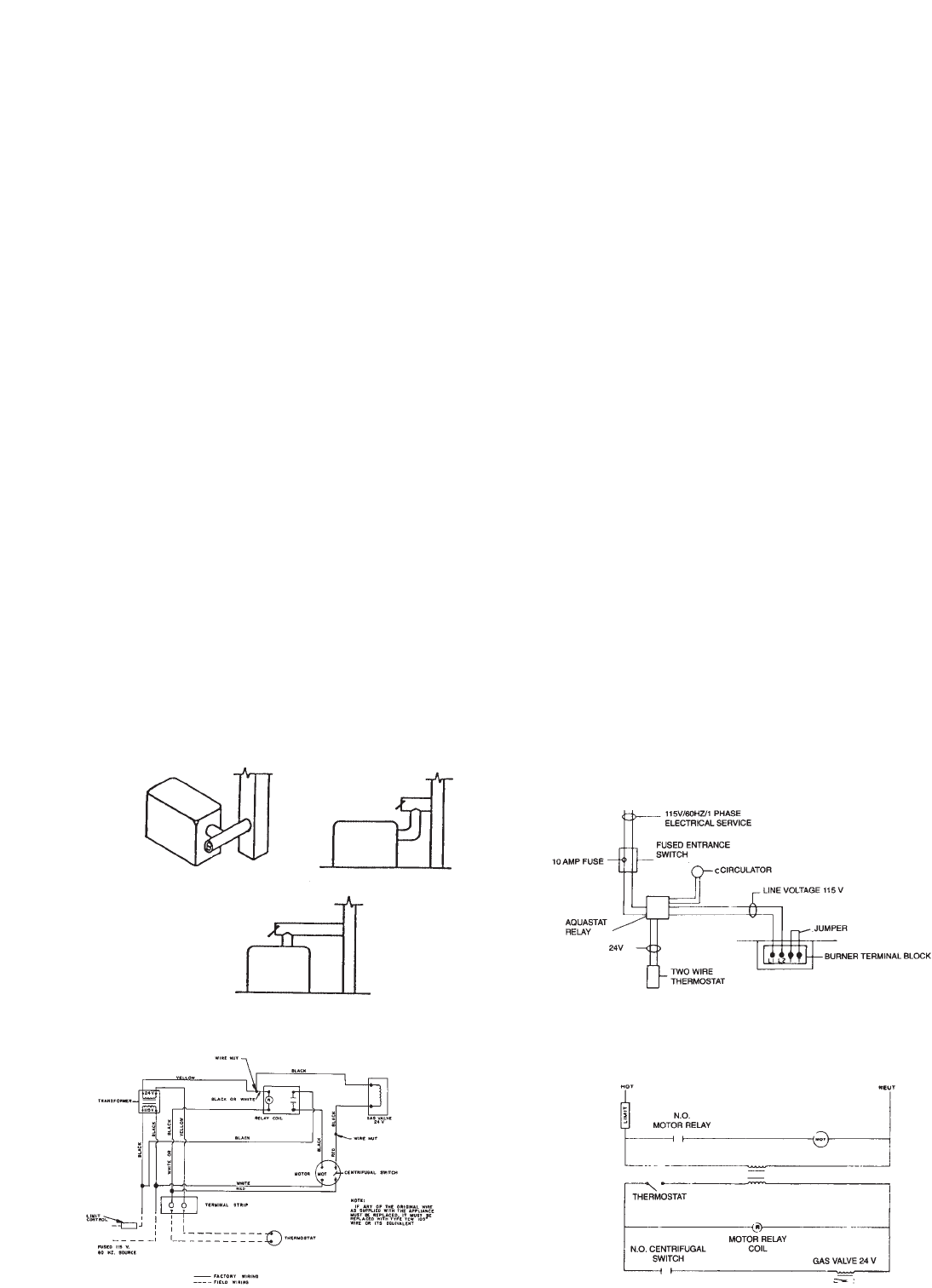
For gad fired equipment requiring a double acting barometric the preferred location of the barometric draft control is part of
the bullhead tee shown in figures A, B OR C. During normal operation, flue gases make a right angle turn behind the control,
but do not infringe upon it. Should a downdraft occur, air flowing n the opposite direction strikes the control directly, causing it to
open outwardly and vents the air into the room with a minimum of resistance. Entrained products of combustion are thus
provided grater relief.
BEST LOCATIONS FOR GAS
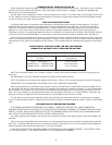
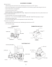
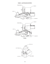
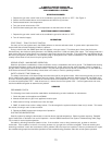
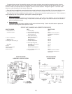
WIRING DIAGRAM LADDER FORM
WIRING DIAGRAM FOR GAS BURNER WITH STANDING PILOT
WIRING DIAGRAM LADDER FORM
FIG. A FIG. B
FIG. C
FIGURE 12
FIGURE 13