


A. Oven connected to correct voltage.
1) L1 (HOT) to power switch (S1).
2) L2 (NEUTRAL or SECOND LINE) to
one side of the following components:
power ON light, heat light, temperature
control board terminal T2 (120VAC) or
terminal T3 (208- 240VAC), oven
cavity lights, buzzer, "Cook" timer
motor, heat relay coil (R3), convection
fan motor common ©), transformer
primary (T1), motor speed (Hi/Low)
switch and the component cooling fan.
B. Oven properly grounded.
C. Gas supply valve ON.
D. Gas combination control valve ON.
E. Power switch (S1) OFF.
F. Oven light switch (S2) ON/OFF (position
has no affect on the function of the "Cook"
cycle).
G. Temperature control dial set to lowest
temperature (fully counterclockwise).
H. High limit switch CLOSED.
I. Timer in the OFF position.
J. Oven doors Closed.
1) Door switch contacts CLOSED.
K. Oven cavity temperature below 140°F.
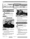
2. Set temperature control dial to desired
temperature.
3. Power switch (S1) turned ON.
A. Component cooling fan energized.
B. Power ON light (Amber) comes ON.
C. Power to one side of the following
components: Timer terminal 1, transformer
primary (T1).
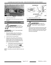
NOTE: Power is available to the oven light switch
(wire #20) to turn the oven cavity lights ON when the
light switch is turned ON; and power is available to the
normally open N.O. side (wire #28) of the door switch
contacts and connects power to additional
components when the door switch contacts are
CLOSED (door closed).
1) Transformer (T1) energized.
a. Power (24VAC) to one side of the
following components: heat relay
(R3) normally open (N.O.)
contacts, high limit --- connected
through the normally closed
(N.C.) contacts to the 1st valve
(safety) on the dual solenoid gas
valve.
a) 1st valve (safety) on the gas
valve energized.
NOTE: Gas does not flow to the burner until the 2nd
valve (main) is energized.
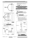
2) With door switch closed, power is
applied to motor speed switch (Hi/
Low).
a. When the convection fan motor
reaches operating speed, the
centrifugal switch (N.O.) on the
motor closes.
b. Power to normally open (N.O.)
side of internal relay contacts
(terminal 7) on the temperature
control board.
3) Power is also connected back through
a second set of contacts on the power
switch (S1) to terminal 8 on the
temperature control board.
a. Solid state temperature control
energized. If the oven
temperature is below set point,
the temperature control will
energize its internal relay. The
normally open (N.O.) contacts
close and apply power to the
following components:
a) Heat light (clear) comes ON.
b) Power is connected through
the centrifugal switch
contacts on the convection
fan motor, heat relay (R3) is
energized, (R3) contacts
(N.O.) close and the heating
circuit is powered.
c) Ignition control module is
energized.
SG SERIES GAS CONVECTION OVENS - ELECTRICAL OPERATION
Page 29 of 33 F45525 Rev. A (0315)