


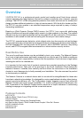
VIVOTEK - A Leading Provider of Multimedia Communication Solutions
6 - User's Manual
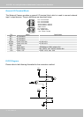
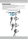
General I/O Terminal Block
This Network Camera provides a general I/O terminal block which is used to connect external
input / output devices. The pin denitions are described below.
Pin Name Specification
N�C� No Connector
N�C� No Connector
N�C� No Connector
AC24V Power in AC 24V AC 24V ± 5%
AC24V Power in AC 24V AC 24V ± 5%
GND Ground
DI Digital Iutput OPEN/Short-to-GND, isolation 2kV
DO Digital Output Max� 40VDC, max� 400mA, isolation 2kV
+12V Power +12V 12VDC ± 10%, max� 0�4A
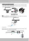
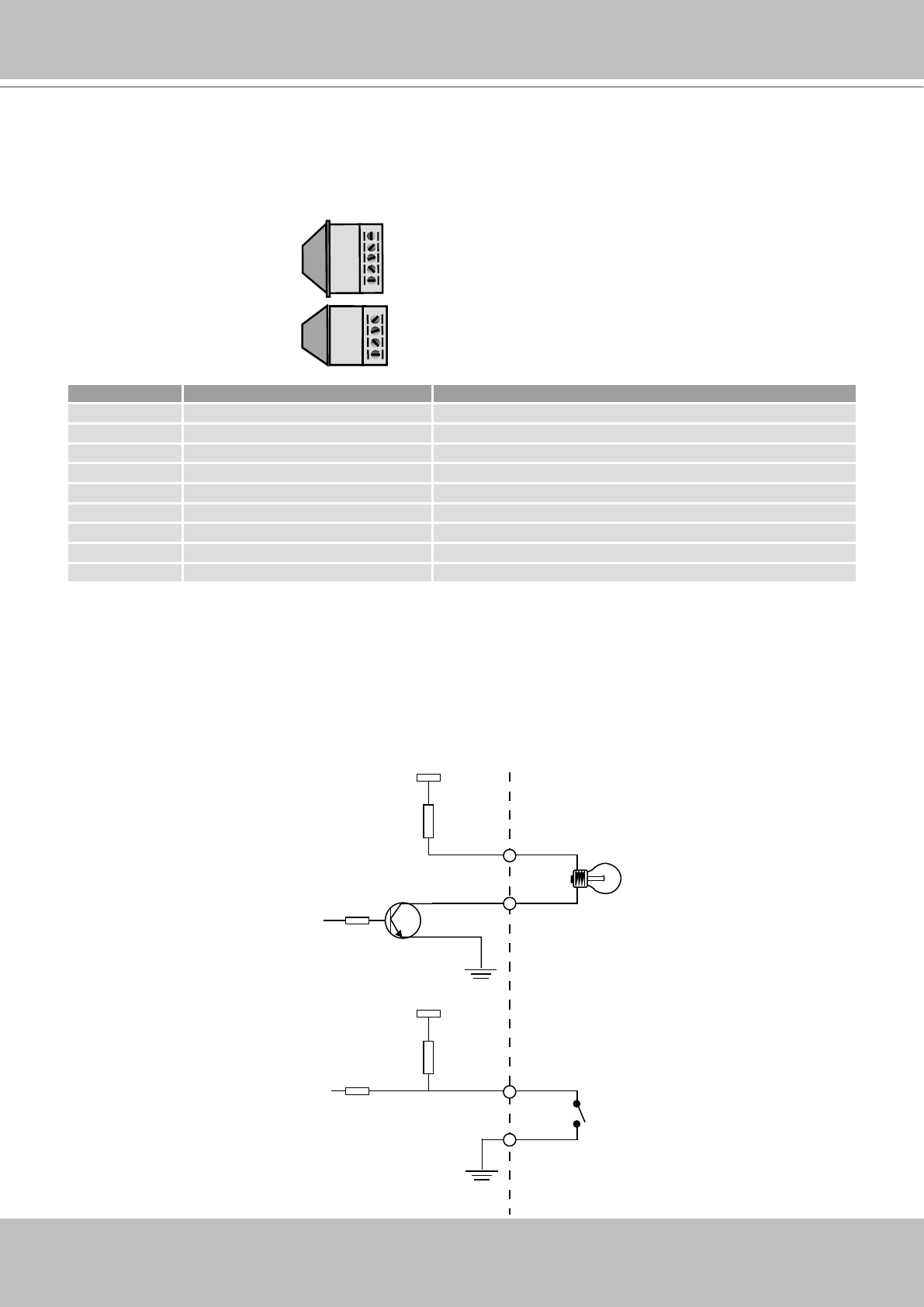
DI/DO Diagram
Please refer to the following illustration for the connection method�
N.C.
N.C.
N.C.
AC24V
AC24V
GND
DI
DO
+12V
N�C�: No Connector
N�C�: No Connector
N�C�: No Connector
AC24V: Power in AC 24V
AC24V: Power in AC 24V
GND: Ground
DI : Digital Input
DO : Digital Output
+12V : Power, 12V DC
12V
+12V
Digital output
PIN 1
Power+12V
PIN 2
Digital input
PIN 3
Ground
PIN 4