


SECTION TSM 845 ISSUE F PAGE 9 OF 14
Use a suitable lubricant compatible with the fluid being
handled when reassembling the pump.
Inspect all parts, especially drilled holes in casing for the suck
back system to make sure they are not plugged. Replace any
worn parts and polish any burrs; clean all parts; assemble
pump.
1. If the canister O-rings need to be replaced, apply a
lubricant to the O-ring and place into the O-ring groove.
If the O-ring is PTFE (derivative) encapsulated, follow
these special instructions.
Do not attempt to reuse the primary O-ring if it has been
removed (and is PTFE derivative encapsulated). Immerse a
new O-ring in boiling water and stretch out O-ring so it will
fit onto casing hub without forcing over a sharp edge. Run
hot water over O-ring until it shrinks down tight onto the pilot
of the pump. Dry with compressed air. The secondary PTFE
derivative encapsulated O-ring can be placed in the bracket
groove with some lubricant.
2. If casing was removed from bracket, inspect flat
gasket and replace if necessary. Install casing onto
bracket pilot in the same orientation as before. This
series of pumps does not allow rotating the casing
to alternate port configurations – to modify the port
arrangement, Refer to “Pump Rotation” on page 10.
Secure the casing with (8) capscrews.
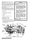
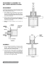
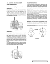
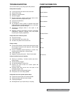
3. Place the balance plate (if separate from bracket) into
the casing bore (this step may not be required in the
825 series). Make sure plate is positioned the same as
before. Refer to Figure 15 for standard balance plate
positioning.
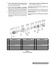
ASSEMBLY: PUMP
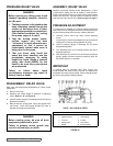
GASKET TABLE
FIGURE 15
PUMP MODEL
NORMAL END
CLEARANCE
(iNCH.)
SET OF GASKETS
CONSISTS OF THE
FOLLOWING
K & KK 825 .008
(1) .015
(2) .007
(3) .005
K & KK 823, 827 .010
TABLE 2
As a general guideline, for viscosity’s between 750 and
7500 SSU (heavier lube oils) double the amount of end
clearance indicated, for viscosity’s between 7500 and
25,000 SSU (e.g., resins) triple the amount indicated.
For specific recommendations for end clearances for
viscosity or for operating temperatures above 225ºF,
check with your Viking Representative or consult the
factory.
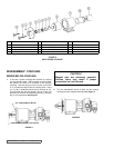
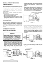
6. Coat the idler pin with a suitable lubricant and place the
idler on the idler pin in the head.
7. The head can now be assembled on the pump. Tilt the
top of the pump head away from the pump slightly until
the crescent enters the inside diameter of the rotor and
rotate the idler until its teeth mesh with the rotor teeth.
Pump head and casing should have been marked before
disassembly to insure proper reassembly. If not, be sure
idler pin, which is offset in the pump head, is positioned
toward and an equal distance from port connections to
allow for proper flow of liquid through the pump.
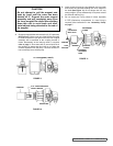
8. Install relief valve if provided and removed. Valve cap
should point to Suction side of the pump (See Figure 3
on page 2).
9. Place key and external retaining ring onto shaft then
follow instruction listed for assembling to the coupling.
5. If old gaskets are not reusable, refer to “Adjusting
Head Gasket End Clearance” on page 10. Otherwise,
place the head gaskets on the head. The proper amount
of gaskets should be used to provide the correct end
clearance. Table 2 gives the quantity of gaskets available
in a gasket set along with standard end clearance.
End clearances are adequate for viscosity’s up to 750 SSU
(SAE 20-lube oil at room temperature). Higher viscosity
liquids require additional end clearances.
4. Clean rotor and shaft so it is free of dirt, grit and other
debris and apply lubricant. Push into casing and bracket
bushings as far as it will go.
STANDARD POSITION
CW ROTATION AS
VIEWED FROM HEAD
DISCHARGE
PORT
GROOVE
SUCTION
PORT