


SECTION TSM 845 ISSUE F PAGE 3 OF 14
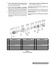
Series 823, 825 and 827 pumps are designed for long,
trouble-free service life under a wide variety of application
conditions with a minimum of maintenance. The points listed
below will help provide long service life.
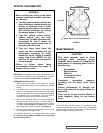
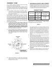
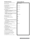
FIGURE 3
SPECIAL INFORMATION
CAUTION !
Rare earth magnets used in these
couplings have extremely strong
magnetic fields capable of changing the
performance or damaging items such as
the following:
Pacemakers
Metal Implants
Watches
Computers & discs
Credit Cards
Completely assembled magnetic
couplings will not affect items listed
above.
Altered performance or damage can
occur only when the coupling halves are
separated.
There are no known harmful effects of
these magnetic fields on the human
body.
MAINTENANCE
ROTATION: Viking Mag-Drive® pumps are designed to run
in the direction indicated on the nameplate only. If rotation
must be reversed, see “Pump Rotation” on page 10.
PRESSURE RELIEF VALVES:
1. Relief valves are mounted on the head of K and KK
size pumps. Relief Valves are not available on jacketed
heads.
2. If a Relief Valve is not furnished on the pump, some
means of over protection such as an in-line relief valve
should be provided. Do not rely on magnets decoupling
for protection from over pressure. This may result in
damage to magnets, pump or other equipment.
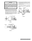
3. Relief valve adjusting screw cap must always point
towards suction side of pump. If pump rotation is
reversed, remove pressure relief valve and turn end for
end (See “Pump Rotation” on page 10 for additional
steps required for proper operation). See Figure 3.
4. Pressure relief valves cannot be used to control pump
flow or regulate discharge pressure.
For additional information on pressure relief valves, refer
to Technical Service Manual TSM000 and Engineering
Service Bulletin ESB-31.
DANGER !
Before opening any Viking pump liquid
chamber (pumping chamber, reservoir,
etc.) Be sure:
1. That any pressure in the chamber has
been completely vented through the
suction or discharge lines or other
appropriate openings or connections.
(See detailed procedure for venting
the pumps, pages 4, 5 and 6).
2. That the driving means (motor,
turbine, engine, etc.) has been
“locked out” or made otherwise non-
operational so that it cannot be
inadvertently started while work is
being done on the pump.
3. That you know what liquid the
pump has been handling and the
precautions necessary to safely
handle the liquid. Obtain a material
safety data sheet (MSDS) for the
liquid to be sure these precautions
are understood.
Failure to follow above listed
precautionary measures may result in
serious injury or death.
SUCTION
DISCHARGE
RELIEF VALVE ADJUSTING SCREW CAP