


SECTION TSM 845 ISSUE F PAGE 6 OF 14
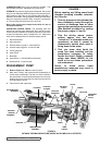
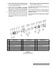
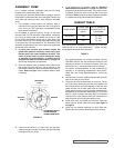
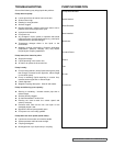
ITEM NAME OF PART ITEM NAME OF PART ITEM NAME OF PART
1 Capscrews 5 Ball Bearing (2 Req’d) 9 Bracket
2 External Snap Ring 6 Internal Snap Ring 10 Canister
3 Bearing Housing 7 Key 11 Inner Magnet Assembly
4 Bearing Spacer 8 Outer Mag Assembly 12 Hand Knobs
FIGURE 6
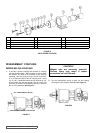
MD-C SERIES COUPLING
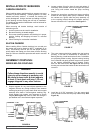
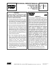
1. If unit has a spacer coupling then bracket of coupling
can stay bolted to base. Without spacer coupling, either
the reducer will need to be removed or the coupling
unbolting. Remove piping to pump, provide a minimum
of 4” of clearance beyond end of coupling shaft. Insert
(2) .5” U.N.C. handknobs which have a minimum of 4.5”
of full threads into the two tapped holes at 9 and 3.00
positions on the back of the bearing housing. Remove
the (4) .375 capscrews. See Figure 7.
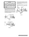
DISASSEMBLY: COUPLING
SERIES MD-C80 COUPLING
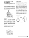
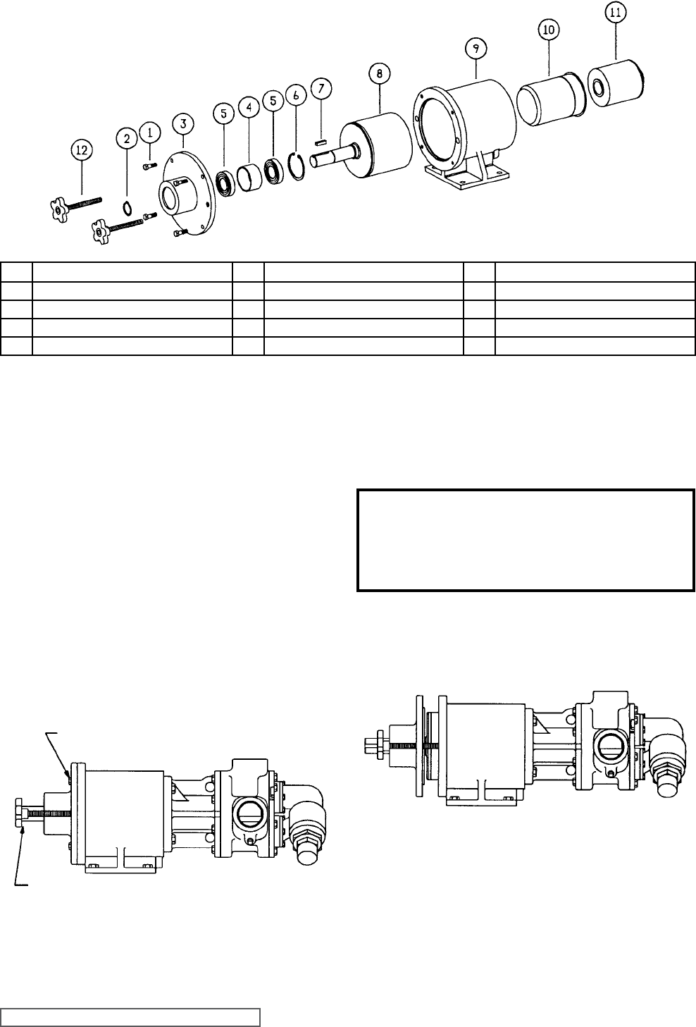
CAUTION !
Magnet sets are extremely powerful.
Serious injury may result if proper
procedures are not followed.
2. Turn the handwheels evenly to back out the bearing
housing and outer magnet assembly. See Figure 8.
FIGURE 7
FIGURE 8
.375” CAPSCREWS (4 REQ’D)
HAND KNOBS (2 REQ’D) 2-790-046-999