


SECTION TSM 845 ISSUE F PAGE 10 OF 14
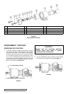
INSTALLATION OF BUSHINGS
CARBON GRAPHITE:
SILICON CARBIDE
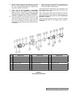
ASSEMBLY COUPLING:
SERIES MD-C80 COUPLING
When installing carbon graphite bushings, extreme care must
be taken to prevent breaking. Carbon graphite is a brittle
material and easily cracked. If cracked, the bushing will
quickly disintegrate. Using a lubricant and adding a chamfer
on the bushing and the mating part will help in installation.
The additional precautions listed below must be followed for
proper installation:
When removing old bracket bushings, mark location of
lubrication groove.
1. An arbor press must be used for installation.
2. Be certain bushing is started straight.
3. Do not stop pressing operation until bushing is in proper
position, starting and stopping will result in a cracked
bushing.
4. Check bushing for cracks after installation.
When installing Silicon Carbide bushings into a metal part
the mating part must be heated to 600° F (preferable in an
oven). The bushing must be put into the proper position
quickly before the mating part cools down and the bushing
heats up. Failure to follow this procedure will result in cracked
bushings.
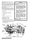
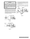
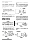
1. Inspect magnets for any steel objects attached to the
magnets. Remove any foreign material. Place external
retaining ring and key on pump shaft. Slide inner magnet
assembly onto shaft so it butts against retaining ring.
Install washer, lock washer and capscrew to secure
magnet (See Figure 16). Insert a brass bar through a
port between two rotor teeth and tighten capscrew.
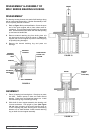
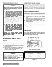
4. The outer magnet should be installed into the bearing
housing, if not refer to Disassembly & Assembly of
Bearing Housing. Install hand knobs so that 4” of threads
are projecting below housing. Support bearing housing
from overhead and gently position magnet over canister
so the magnet assemblies start to engage. Evenly
back out the hand knobs. See Figure 18. the bearing
housing move toward the bracket as the hand knobs are
removed.
DANGER !
Follow these directions exactly to avoid
injury to self or damage to pumping unit.
Be careful to keep inner & outer magnets
at least (1) foot apart until step 3. Do not
engage magnets in any other fashion.
FIGURE 16
FIGURE 17
FIGURE 18
FIGURE 19
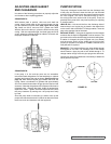
2. Inspect canister O-ring for signs of wear and replace if
necessary. Slide canister over inner magnet and press
over O-ring until canister meets the pump mounting
flange.
3. Support the pump from overhead and secure coupling
bracket to avoid tipping when pump is attached. Using
the canister as a guide, slide the pump assembly up
to the coupling bracket through the smaller opening.
Secure with the four 0.5” capscrews. See Figure 17.
5. Install the (4) 0.375” capscrews. Turn the output shaft
over by hand to make sure the pump rotates freely. See
Figure 19).
0.375” CAPSCREWS
(4 REQUIRED)
PUMP - BRACKET CAPSCREWS
(4 REQUIRED)
CANISTER
0.44”
CAPSCREW
WITH HOLE
LOCK
WASHER
WASHER
INNER
MAGNET
PRIMARY O-RING
EXTERNAL
RETAINING
RING
SECONDARY O-RING