


6
®
B-VENT FREESTANDING FIREPLACE
105500
FREESTANDING
FIREPLACE
ASSEMBLY
Continued
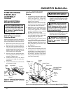
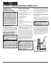
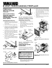
Figure 12 - Attaching Stove Door
Step
Bolt
Door
Hinge
Threaded
Hole
Stove
Door
Stove Bottom
Bolt
Shoulder
Adjusting Nut
Bolt Stop
Catch Bolt
Door Claw
Door
Figure 13 - Catch Bolt and Door Claw
Orientation
10. Attach stove door by inserting step bolt
through door hinge pivot hole and into
threaded hole in stove body (see Fig-
ures 9 and 12). Use an adjustable
wrench or a 12mm socket to fasten step
bolt. Tighten step bolt until snug. Make
sure door moves freely.
11. Install door catch bolt (M8 x 1.25-
55mm with two M8 hex nuts) into
threaded hole on stove body (see Fig-
ure 9). Use an adjustable wrench or a
12mm socket. The catch bolt has two
hex nuts attached to it (see Figure 13).
The top nut is a bolt stop and the bot-
tom nut is for door leveling adjustment.
12. Check general catch bolt alignment
with door claw. Make final adjustment
and door leveling after stove is in nor-
mal standing position.
13. Carefully lift stove back up on its four
attached legs.
14. Set top grate into stove top.
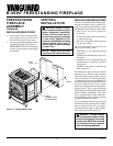
INSTALLING FIREPLACE
INTO STOVE BODY
1. Carefully lift firebox and place into
stove body from the rear of stove.
2. Using screws provided, attach firebox
to back of stove.
Figure 14 - Installing Firebox Into Cast
Iron Stove Body
L
O
H
I
P
I
L
O
T
O
F
F
O
N
Cast Iron
Stove Body
Screw
Insert
Assembly
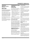
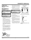
Figure 10 - Attaching Stove Legs
Bottom Of
Stove Unit
Leg
Bolt
Washers
Figure 11 - Attaching Stove Bottom
Bottom Of
Stove Unit
Bolt
Washers
Stove Bottom
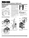
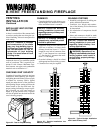
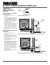
Figure 9 - Locating Threaded Holes for
Stove Bottom, Legs, and Door Attachment
Door Hinge Step
Bolt Hole
Door Catch Bolt
With Adjustable
Hex Nuts Hole
Leg
Hole
Leg Hole
Leg
Hole
Stove
Bottom
Hole
Front
Bottom Of
Stove Unit