


10
®
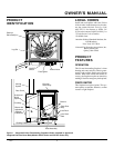
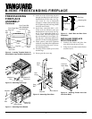
B-VENT FREESTANDING FIREPLACE
105500
VENTING
INSTALLATION
Continued
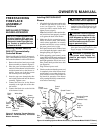
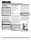
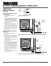
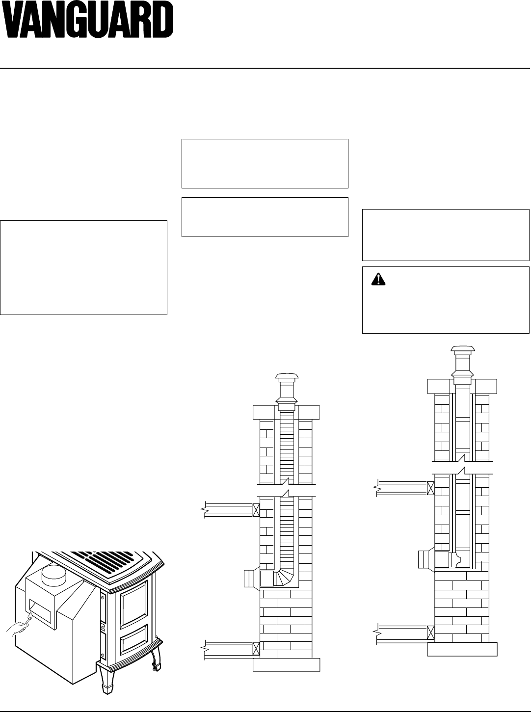
CHECKING VENT CAPACITY
Complete all gas piping, electrical, and vent
connections. After adjusting the fireplace
and lighting the main burners, allow a couple
of minutes for warm-up. Hold a lighted
match just under the rim of the draft hood
relief opening. Proper venting will draw the
flame toward or into the draft hood. Im-
proper venting, indicated by escape or spill-
age of burned gas, will cause match to
flicker or go out. Smoke from a cigarette
will also be pulled into the draft hood if the
vent is drawing properly.
Figure 22 - Test for Proper Venting
• Complete familiarity with chimney con-
dition, height, size, clearance to combus-
tibles and other factors is essential.
CHIMNEYS
NOTICE: Consult the authority
having jurisdiction in your area
regarding masonry chimney vent-
ing applications.
NOTICE: A complete chimney
inspection by a qualified person
should be performed.
• Appliances using B-vent connectors to
vent into a masonry or factory-built
chimney should not exceed 1
1
/2 feet in
length for every inch of connector diam-
eter (3" vent connector has a maximum
4
1
/2 foot length; 5" connector has maxi-
mum 7
1
/2 foot length).
• Oversized chimneys should be relined
with appropriate listed relining systems.
• Cleanout access may be required.
NOTICE: Consult the authority
having jurisdiction in your area
regarding listed chimney liner
venting applications.
WARNING: Operation of im-
properly installed and maintained
venting system could result in
serious injury, property damage,
or loss of life.
RELINING SYSTEMS
• Suitability and approval of relining ma-
terials should be determined.
• Condition, size, height, and termina-
tion of the chimney to be relined must
be determined.
• No substitution of components should
be made.
• Joints and connectors should be made
according to manufacturer’s instructions.
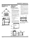
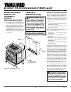
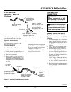
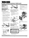
Figure 23 - Straight Installation into
Masonry Chimney
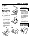
Figure 24 - Typical Straight Installation
with Listed Chimney Liner
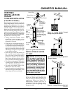
INSTALLING VENT SYSTEM
IN A CHASE
A chase is a vertical box-like structure built
to enclose venting that runs along the out-
side of a building. A chase is not required for
such venting.
NOTICE: Treatment of firestops
and construction of the chase
may vary from building type to
building type. These instructions
are not substitutes for the re-
quirements of local building
codes. You must follow all local
building codes.
Note:
When installing in a chase, you should
insulate the chase as you would the outside
walls of your home. This is especially im-
portant in cold climates. Minimum clear-
ance between vent pipes and combustible
materials such as insulation is 1".