


CAC 9
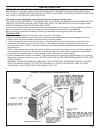
Two common types of clearance reductions systems use sheet metal with a thickness of 28 gauge (galvanized steel, aluminum,
copper) or a 3-1/2 inch (4 inch thick nominal) thick masonry wall. Either of these materials must be spaced out 1 inch from the
combustible surfaces. With sheet metal, noncombustible spacers are used to maintain the 1 inch air space. With a masonry
wall, metal wall ties and furring strips, if needed, are used to anchor the brick to the wall. To avoid excessive heat transmission,
the spacers or wall ties should not be placed directly behind the heater or chimney connector. The 1 inch air space provides free
air circulation. It is essential that there be openings at the top and bottom of these clearance reducers so cool air can enter at the
bottom and warm air exit at the top. It is the “chimney effect” whereby when the air in the space is heated, it rises exiting from the
top and being replaced by cooler air at the bottom, that makes these shields effective.
Masonry, or other noncombustible products, attached directly to a combustible surface without an air space offer very little
protection and cannot be considered a clearance reduction system unless specific materials have been tested and listed for
direct attachment to a combustible surface. The same applies to thin veneer brick and stone coverings. These materials provide
adequate protection only when mounted on sheet metal with a 1 inch minimum spacing to the wall.
A variety of prefabricated clearance reduction systems which have been safety tested and listed are available through heater
dealers. Always look for a safety listing label on the product when selecting a clearance reduction system through a heater
dealer and make sure it is designed for use with solid fuel. The manufacturers of these tested and listed systems provide specific
installation instructions that must be followed exactly for a safe installation.
Should you chose to make your own clearance reduction system, contact your local fire department, fire marshal or building code
inspector for specific requirements regarding home-constructed clearance reduction systems and safe installation clearances to
protected combustible surfaces.
TO SAFELY AND PROPERLY INSTALL THIS HEATER:
1. Install a Listed High Temperature Type HT Factory-built Residential Type and Building Heating Appliance Chimney, build a
masonry chimney or adapt an existing chimney to vent the heater. (See the CHIMNEY CONNECTOR AND CHIMNEYS section
of this manual for important information).
2. Purchase the 6-inch diameter chimney connector pipes that are required. The pipe should be black or blued steel, 24 gauge
minimum. If elbows are needed, use only seamless elbows because seamed elbows can leak smoke. Do not use more that two
elbows or the chimney draft will be restricted (See the CHIMNEY CONNECTOR AND CHIMNEYS section of this manual for
details). Number 8 sheet metal screws and furnace cement will also be needed to assemble the chimney connector pipes. If the
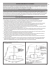
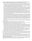
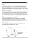
heater is to be installed to a masonry fireplace as shown by figure 4, you should also obtain the fireplace items called for by
figure 4.
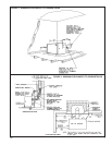
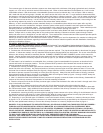
3. If the heater is to be installed on a combustible floor, purchase a listed noncombustible floor protector as described in this
manual and install it in the proper location. The floor protector MUST protect the floor beneath and around the heater and
chimney connector as shown by figure 5.
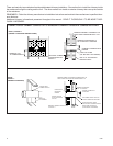
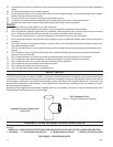
4. Assemble the chimney connector pipe sections to determine if the chimney connector pipe will correctly extend from the
heater flue collar to the chimney. Any horizontal section of chimney connector pipe must slope upward at least 1/4” rise to the
horizontal foot to maintain adequate draft (See figure 6). Always install the chimney connector pipe with the crimped end toward
the heater to prevent creosote from leaking out of the joints (See figure 6). Always use the least number of chimney connector
pipe sections possible. Minimum clearance to combustible walls and ceilings as noted by figures 1 through 4 MUST always be
maintained if a clearance reduction system is not installed.
5. After it is determined that the assembled chimney connector will properly connect the heater to the chimney, disassemble all
sections of the chimney connector in preparation for the final assembly procedures.
6. Place the crimped end of the first chimney connector pipe or elbow into the heater’s flue collar and mark it through each of the
holes in the heater’s flue collar.
7. Remove the pipe or elbow from the flue collar and drill 1/8 inch diameter holes at the points marked by step 6.
8. Apply furnace cement to the inside surface of the heater’s flue collar, reinstall the first pipe or elbow and fasten in place with
No. 8 sheet metal screws. Apply additional furnace cement to the outside of the chimney connector flue collar joint if an airtight
seal was not achieved when the pipe or elbow was installed.
9. Assemble the remaining chimney connector pipes by applying furnace cement to the joints, drilling 1/8 inch diameter holes for
and attaching each joint with three No. 8 sheet metal screws. Wipe all excess furnace cement from the pipe joints with rag or
paper towel. Allow the applied cement to dry before building the first fire in the heater.
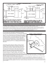
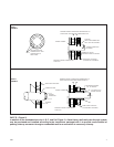
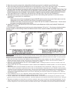
10. Depending on your particular type of installation, connect the heater’s chimney connector to a masonry chimney as shown
by figures 7 or 8, or connect the chimney connector to a metal prefabricated chimney as specified by the instructions furnished
with the metal prefabricated chimney or connect the chimney connector to a masonry fireplace as shown by figure 4.
DANGER: IF ANY CLEARANCE TO UNPROTECTED WALL OR CEILING IS LESS THAN THOSE SPECIFIED BY FIGURES 1
THROUGH 4 AFTER HEATER INSTALLATION IS COMPLETED, A CLEARANCE REDUCTION SYSTEM MUST BE IN-
STALLED BEFORE THE FIRST FIRE IS BUILT IN THE HEATER; OTHERWISE, THE UNPROTECTED WALL OR CEILING
COULD CATCH FIRE. REMEMBER, THERE ARE ALSO LIMITS AS TO HOW CLOSE THE HEATER CAN BE INSTALLED TO
A COMBUSTIBLE SURFACE PROTECTED BY A CLEARANCE REDUCTION SYSTEM. REREAD “MINIMUM CLEARANCES
TO WALLS AND COMBUSTIBLE WALLS AND CEILINGS” PRESENTED EARLIER IN THIS MANUAL.
CAUTION: FOR YOUR SAFETY, CONTACT YOUR LOCAL FIRE DEPARTMENT, FIRE MARSHAL, OR BUILDING CODE
INSPECTOR FOR INSPECTION PRIOR TO AND FOLLOWING CLEARANCE REDUCTION SYSTEM AND/OR HEATER
INSTALLATION.