


8 CAC
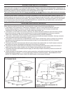
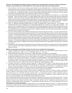
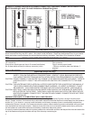
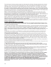
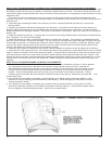
FIGURE 8 - CONNECTING HEATER’S CHIMNEY CONNECTOR TO MASONRY CHIMNEY WHEN CHIMNEY CON-
NECTOR DOES NOT HAVE TO PASS THROUGH A COMBUSTIBLE WALL
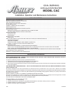
CAUTION: IF THIS HEATER IS NOT PROPERLY INSTALLED, A HOUSE FIRE MAY RESULT. FOR YOUR
SAFETY, FOLLOW THE INSTALLATION DIRECTIONS. CONTACT LOCAL BUILDING OR FIRE OFFI
CIALS ABOUT RESTRICTIONS AND INSTALLATION INSPECTION REQUIREMENTS IN YOUR AREA.
CAUTION: DO NOT CONNECT THIS HEATER TO A CHIMNEY FLUE SERVING ANOTHER APPLIANCE. THERE IS
A SERIOUS SAFETY RISK IF TWO APPLIANCES OR HEATERS ARE CONNECTED TO THE SAME
FLUE.
CAUTION: THE HEATER MUST BE PLACED ON A LISTED FLOOR PROTECTOR AS NOTED IN THIS MANUAL IF
THE FLOOR IS WOOD OR OTHER COMBUSTIBLE FLOORING. IF CARPET IS PRESENT, IT MUST
BE REMOVED. THE FLOOR PROTECTOR MUST NOT BE PLACED ON CARPET. (SEE FIGURE 5).
CAUTION: MOST WALLS AND CEILINGS CONTAIN WOOD EVEN THOUGH THEY ARE MADE OF SHEETROCK
OR PLASTER ON THE OUTSIDE. THESE WALLS AND CEILINGS CAN CATCH FIRE FROM THE HOT
HEATER OR CHIMNEY CONNECTOR IF THE HEATER AND CHIMNEY CONNECTOR ARE NOT PROP-
ERLY INSTALLED.
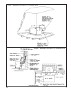
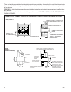
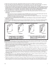
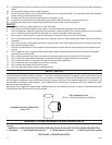
MINIMUM CLEARANCE TO COMBUSTIBLE WALLS AND CEILINGS
Minimum clearances to unprotected combustible walls and ceilings as noted by Figures 1 through 4 must be main-
tained. Drapes, curtains, furniture and other combustible materials should be kept much further away from the heater to
avoid a fire. If you chose to, you may install the heater and chimney connector closer to combustible surfaces than
indicated by Figures 1 through 4 if a clearance reduction system is also installed to protect combustible ceiling and wall
near the heater and chimney connector. However, there are limits as to how close the heater and chimney connector
can be installed to combustible surfaces protected by a clearance reductions system.
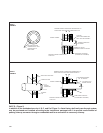
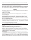
A correctly installed clearance reduction system protects the combustible surfaces well beyond the sides and above the
top of the heater and beyond the sides and top of the chimney connector pipe.
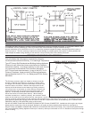
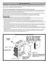
HEATER INSPECTION
Before installing the heater, inspect the heater for external damage and missing parts. Check the gaskets around the
doors to assure that they are still in place. Also check inside the heater. Report any deficiencies found to your heater
dealer and make sure all problems are resolved before installing the heater. See figure 12 for illustration of heater
parts.
TOOLS AND SUPPLIES NEEDED FOR INSTALLATION
Electric drill 1/4 or 3/8 inch drive Can or tube of furnace cement
1/8 inch drill bit Floor protector
Screw driver (blade type and size to fit screws listed below) Rag or several paper towels
No. 8 sheet metal screws (for chimney connector joints) Chimney connector pipes (and elbows, if
required
Ruler or tape measure Pencil
HEATER INSTALLATION