


14 USSC
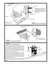
6. Place the crimped end of the first chimney pipe or elbow into the heater's flue collar and mark it through each of the
holes in the heater's flue collar.
7. Remove the pipe or elbow from the flue collar and drill 1/8 - inch diameter holes at the points marked.
8. Apply the furnace to the inside surface of the heater's flue collar, reinstall the first pipe or elbow and fasten in place with
No. 8 sheet metal screws. Apply additional furnace cement to the outside of the chimney connector flue collar joint if an
airtight seal was achieved when the pipe or elbow was installed. Wipe all excess furnace cement from the joint with a rag
or paper towel before the cement dries.
9. Assemble the remaining chimney connector pipes by apply furnace cement to the joints, drilling 1/8-inch diameter
holes for and attaching each joint with three(3) No. 8 sheet metal screws. Wipe all excess furnace cement from the joints
with a rag or a paper towel before the cement dries.
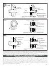
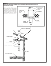
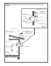
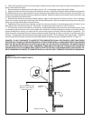
10. Depending on the type chimney installed, connect the chimney connector to the chimney as shown in Figure 5 or as
described by the chimney's manufacturer. Remember , we highly recommend use of UL 103-HT chimney.
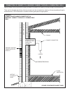
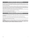
11. If the chimney to which the heater is connected is a metal prefabricated chimney that exits the home at a point 7 feet
or less above ground level and runs up the outside of the residence, it will be necessary to construct a chimney shield to
prevent someone from coming in contact with the outer surface of the hot chimney while the heater is in operation. The
shield should be constructed from wire mesh or expanded metal (22 gauge minimum) to allow air circulation around the
chimney. The openings in the shield should not be large enough to allow a 1/2-inch diameter rod to pass through. The shield
should have sufficient rigidity to provide the required protection and be permanently installed as shown in Figure 10.
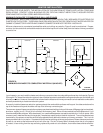
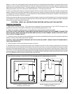
DANGER: IF ANY CLEARANCE TO UNPROTECTED COMBUSTIBLE WALL OR CEILING IS LESS THAN THOSE
SPECIFIED BY FIGURE 8 AFTER HEATER INSTALLATION IS COMPLETED, A CLEARANCE REDUCTION SYSTEM
MUST BE INSTALLED BEFORE THE FIRST FIRE IS BUILT IN THE HEATER; OTHERWISE, THE UNPROTECTED
WALL OR CEILING COULD CATCH FIRE. REMEMBER, THERE ARE ALSO LIMITS AS TO HOW CLOSE THE HEATER
CAN BE INSTALLED TO A COMBUSTIBLE SURFACE PROTECTED BY A CLEARANCE REDUCTION SYSTEM. RE-
READ "MINIMUM CLEARANCES TO COMBUSTIBLE WALL AND CEILINGS" PRESENTED EARLIER IN THIS MANUAL.
7 FEET
(SHIELD NOT REQUIRED
BEYOND 7 FEET ABOVE
GROUND LEVEL.)
CHIMNEY
SHIELD
GROUND LEVEL
FIGURE 10 -
INSTALLATION OF CHIMNEY SHIELD